CHAPTER 5: SETPOINTS S4 ELEMENTS
745 TRANSFORMER PROTECTION SYSTEM – INSTRUCTION MANUAL 5–47
SETPOINTS
• Shown as a block with the heading SETPOINT.
• The exact wording of the displayed setpoint message identifies the setpoint.
• Major functional setpoint selections are listed below the name and are incorporated in
the logic.
MEASUREMENT UNITS
• Shown as a block with inset labelled RUN.
• The associated pickup or dropout setpoint is shown directly above.
• Operation of the detector is controlled by logic entering the RUN inset.
• Relationship between setpoint and input parameter is indicated by simple
mathematical symbols: <, >, etc.
TIME DELAYS
• Shown as a block with the following schematic symbol: .
• The delay before pickup is indicated by t
PKP,
and the delay after dropout is indicated
by t
DO
.
• If the delay before pickup is adjustable, the associated delay setpoint is shown directly
above, and the schematic symbol indicates that t
PKP
= DELAY.
LED INDICATORS
• Shown as the following schematic symbol: ⊗.
• The exact wording of the front panel label identifies the indicator.
LOGIC
• Described using basic AND gates and OR gates
5.6.2 Setpoint Group
PATH: SETPOINTS S4 ELEMENTS SETPOINT GROUP
Each protection and monitoring element setpoint (programmed in S4 ELEMENTS) has four
copies, and these settings are organized in four setpoint groups. Only one group of settings
are active in the protection scheme at a time. The active group can be selected using the
ACTIVE SETPOINT GROUP setpoint or using a logic input. The setpoints in any group can be
viewed or edited using the
EDIT SETPOINT GROUP setpoint.
• ACTIVE SETPOINT GROUP: Select the number of the
SETPOINT GROUP whose settings
are to be active in the protection scheme. This selection will be overridden if a higher
number setpoint group is activated using logic inputs.
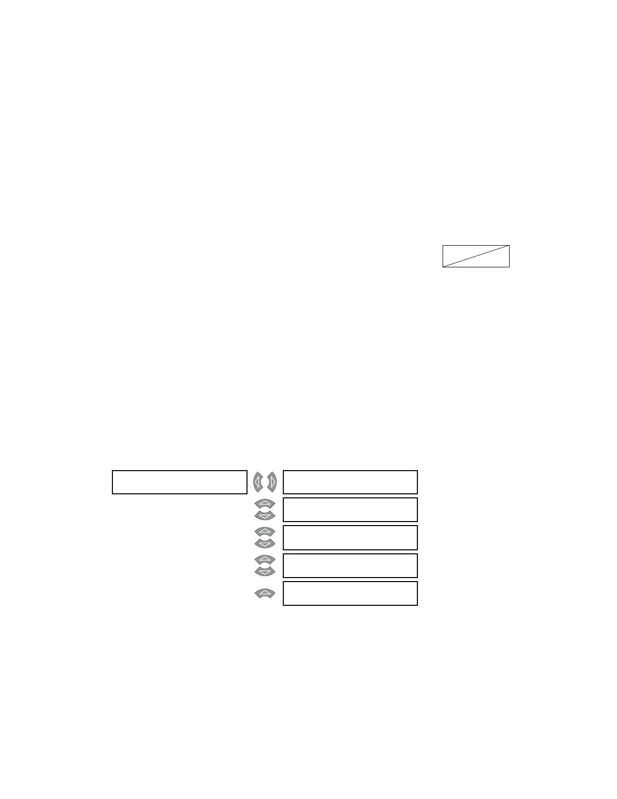
SETPOINT GROUP [] ACTIVE SETPOINT
GROUP: Group 1
Range: Group 1, Group 2, Group 3,
Group 4
MESSAGE
EDIT SETPOINT
GROUP: Active Group
Range: Group 1, Group 2, Group 3,
Group 4, Active Group
MESSAGE
GROUP 2 ACTIVATE
SIGNAL: Disabled
Range: Logic Input 1 to 16, Disabled
MESSAGE
GROUP 3 ACTIVATE
SIGNAL: Disabled
Range: Logic Input 1 to 16, Disabled
MESSAGE
GROUP 4 ACTIVATE
SIGNAL: Disabled
Range: Logic Input 1 to 16, Disabled