5–48 745 TRANSFORMER PROTECTION SYSTEM – INSTRUCTION MANUAL
S4 ELEMENTS CHAPTER 5: SETPOINTS
• EDIT SETPOINT GROUP: Select the number of the SETPOINT GROUP whose settings
are to be viewed and/or edited via the front panel keypad or any of the
communication ports. Selecting “Active Group” selects the currently active setpoint
group for editing.
• GROUP 2(4) ACTIVATE SIGNAL: Select any logic input which, when asserted, will
(remotely) select
SETPOINT GROUP 2(4) to be the active group. This selection will be
overridden if a higher number setpoint group is activated using the
ACTIVE SETPOINT
GROUP
setpoint or another logic input.
5.6.3 Differential Element
5.6.3.1 Main menu
PATH: SETPOINTS S4 ELEMENTS DIFFERENTIAL
This section contains the settings to configure the percent differential element, including
all associated harmonic inhibit features. The 745 provides three independent harmonic
inhibit features:
HARMONIC INHIBIT, which implements an inhibit scheme based on 2nd or
2nd + 5th harmonic which is ‘in-circuit’ at all times;
ENERGIZATION INHIBIT, which allows
changing the characteristics of the inhibit scheme during energization to improve
reliability; and
5TH HARM INHIBIT, which implements an inhibit scheme based on 5th
harmonic only, allowing inhibiting the percent differential during intentional overexcitation
of the system.
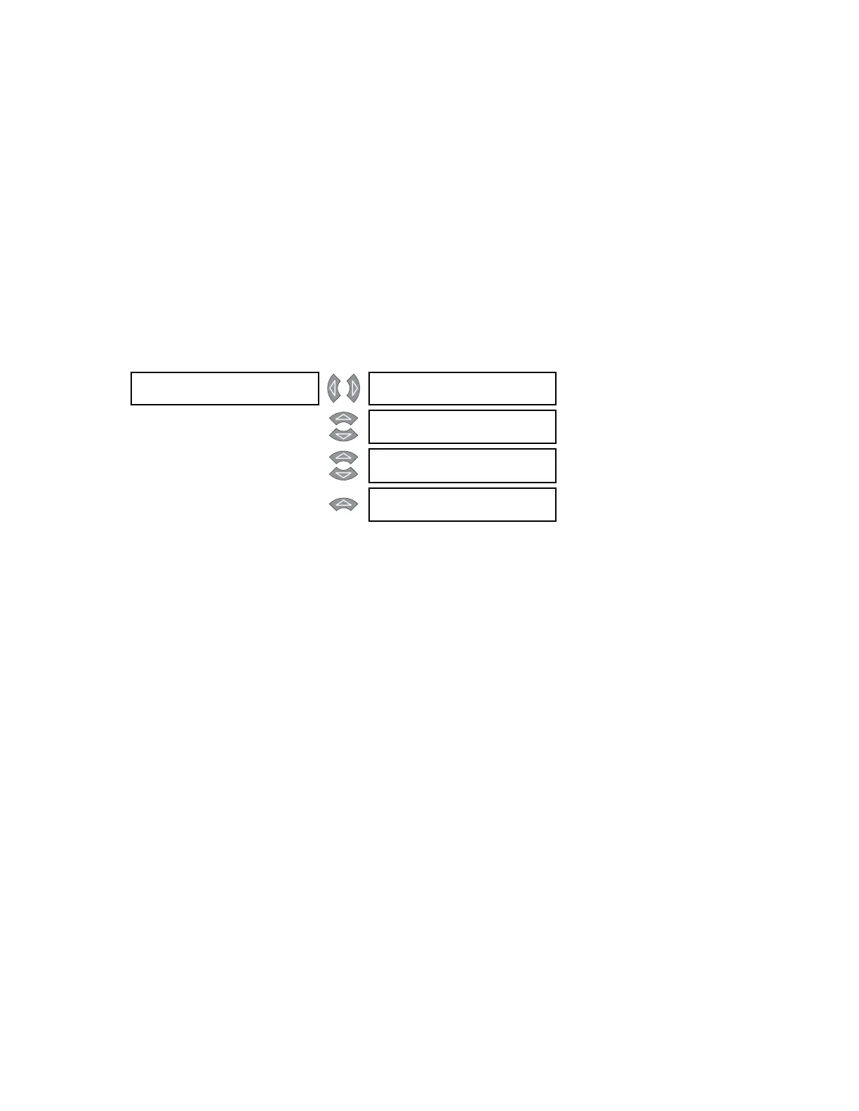
DIFFERENTIAL [] PERCENT []
DIFFERENTIAL
See page 5–49
MESSAGE
HARMONIC []
INHIBIT
See page 5–52
MESSAGE
ENERGIZATION []
INHIBIT
See page 5–53
MESSAGE
5th HARM []
INHIBIT
See page 5–56