5–50 745 TRANSFORMER PROTECTION SYSTEM – INSTRUCTION MANUAL
S4 ELEMENTS CHAPTER 5: SETPOINTS
The basic percent differential operating principle for three-winding transformers is
illustrated by the following equations:
(EQ 5.4)
The basic percent differential operating principle for two-winding transformers is
illustrated by the following equations:
(EQ 5.5)
where I
restraint
= per-phase maximum of the currents after phase, ratio, and zero-
sequence correction;
I
differential
= per-phase vector sum of currents after phase, ratio, and zero-
sequence correction
Note
In the above equations, the 180° phase shift due to the wiring connections is taken into
account, hence the + sign to obtain the differential current.
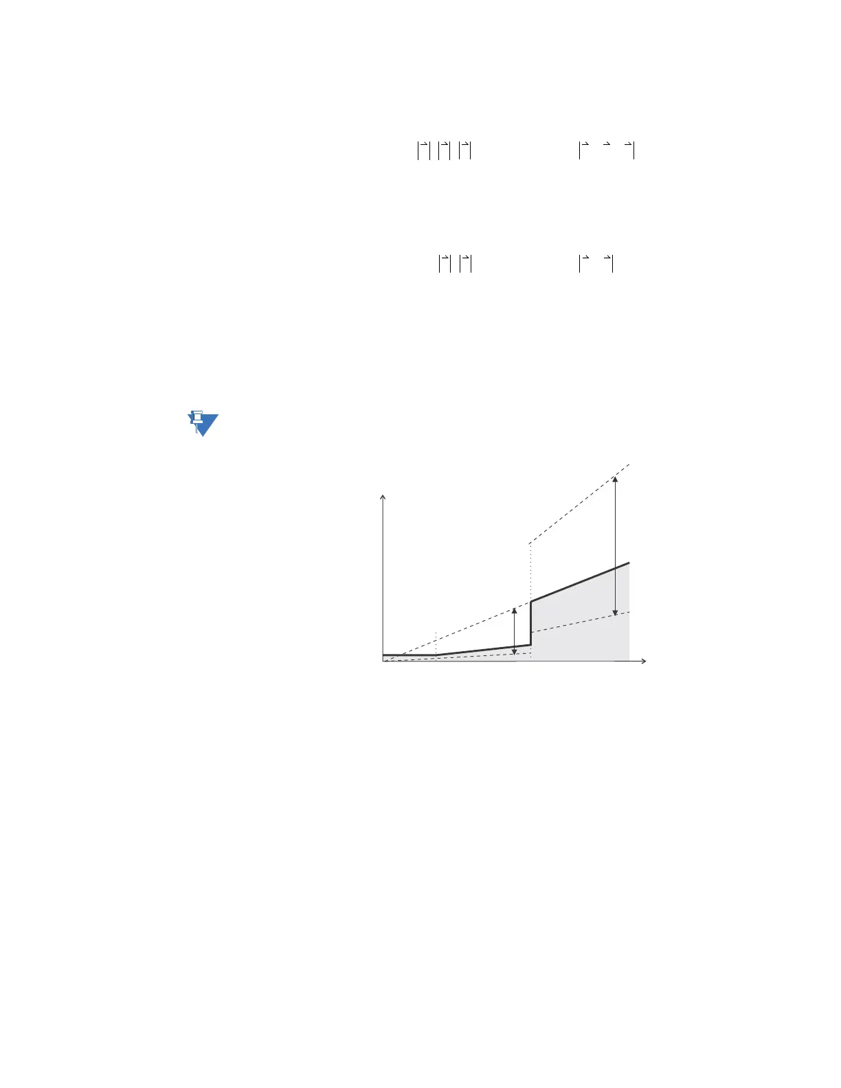
FIGURE 5–8: Percent differential dual-slope characteristic
The base for the percent differential setpoints is the S2 SYSTEM SETUP WINDING 1
WINDING 1 PHASE CT PRIMARY
setpoint value. The percent differential setpoints are
explained below.
• PERCENT DIFFERENTIAL PICKUP: Enter the minimum differential current required for
operation. This setting is chosen based on the amount of differential current that
might be seen under normal operating conditions.
• PERCENT DIFFERENTIAL SLOPE 1: Enter the slope 1 percentage (of differential current
to restraint current) for the dual-slope percent differential element. The slope 1 setting
is applicable for restraint currents of zero to the kneepoint, and defines the ratio of
differential to restraint current above which the element will operate. This slope is set
to ensure sensitivity to internal faults at normal operating current levels. The criteria
for setting this slope are:
I
r
I
restraint
max I
1
I
2
I
3
,,()== ; I
d
I
differential
I
1
I
2
I
3
++==
%slope
I
d
I
r
----
100%×=
I
r
I
restraint
max I
1
I
2
,()== ; I
d
I
differential
I
1
I
2
+==
%slope
I
d
I
r
----
100%×=
100%
OPERATE
REGION
RESTRAINT
REGION
SLOPE 1
25%
SLOPE 2
100%
200%
50%
I (x CT)
restraint
I (x CT)
differential
15%
0.05
1.00
PICKUP 0.30
2.0
KNEEPOINT