CHAPTER 5: SETPOINTS S4 ELEMENTS
745 TRANSFORMER PROTECTION SYSTEM – INSTRUCTION MANUAL 5–51
– To allow for mismatch when operating at the limit of the transformer’s onload
tap-changer range.
– To accommodate for CT errors.
• PERCENT DIFFERENTIAL KNEEPOINT: Enter the kneepoint for the dual-slope percent
differential element. This is the transition point between slopes 1 and 2, in terms of
restraint current, in units of relay nominal current. Set the kneepoint just above the
maximum operating current level of the transformer between the maximum forced-
cooled rated current and the maximum emergency overload current level.
• PERCENT DIFFERENTIAL SLOPE 2: Enter the slope 2 percentage (of differential current
to restraint current) for the dual-slope percent differential element. This setting is
applicable for restraint currents above the kneepoint and is set to ensure stability
under heavy through fault conditions which could lead to high differential currents as
a result of CT saturation.
Note
Since , the differential current is not always greater than
100% of the restraint current. Because of this enhancement, the
PERCENT DIFFERENTIAL
SLOPE 2
setting may cause slow operation (in rare cases no operation) in the following
situations:
1.
PERCENT DIFFERENTIAL SLOPE 2 is set above 100%.
2. The source is connected to one winding only.
Therefore, the
PERCENT DIFFERENTIAL SLOPE 2 value cannot be greater than 100%. To
increase dependability, the Slope 2 settings should be less than 98%
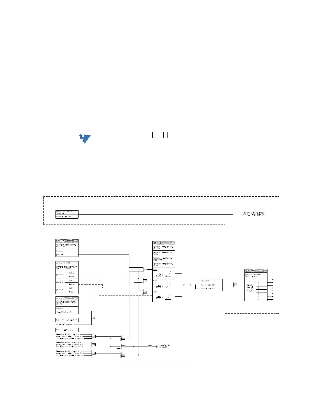
FIGURE 5–9: Percent differential scheme logic
I
restraint'
max I
1
I
2
I
3
,,()=