5–64 745 TRANSFORMER PROTECTION SYSTEM – INSTRUCTION MANUAL
S4 ELEMENTS CHAPTER 5: SETPOINTS
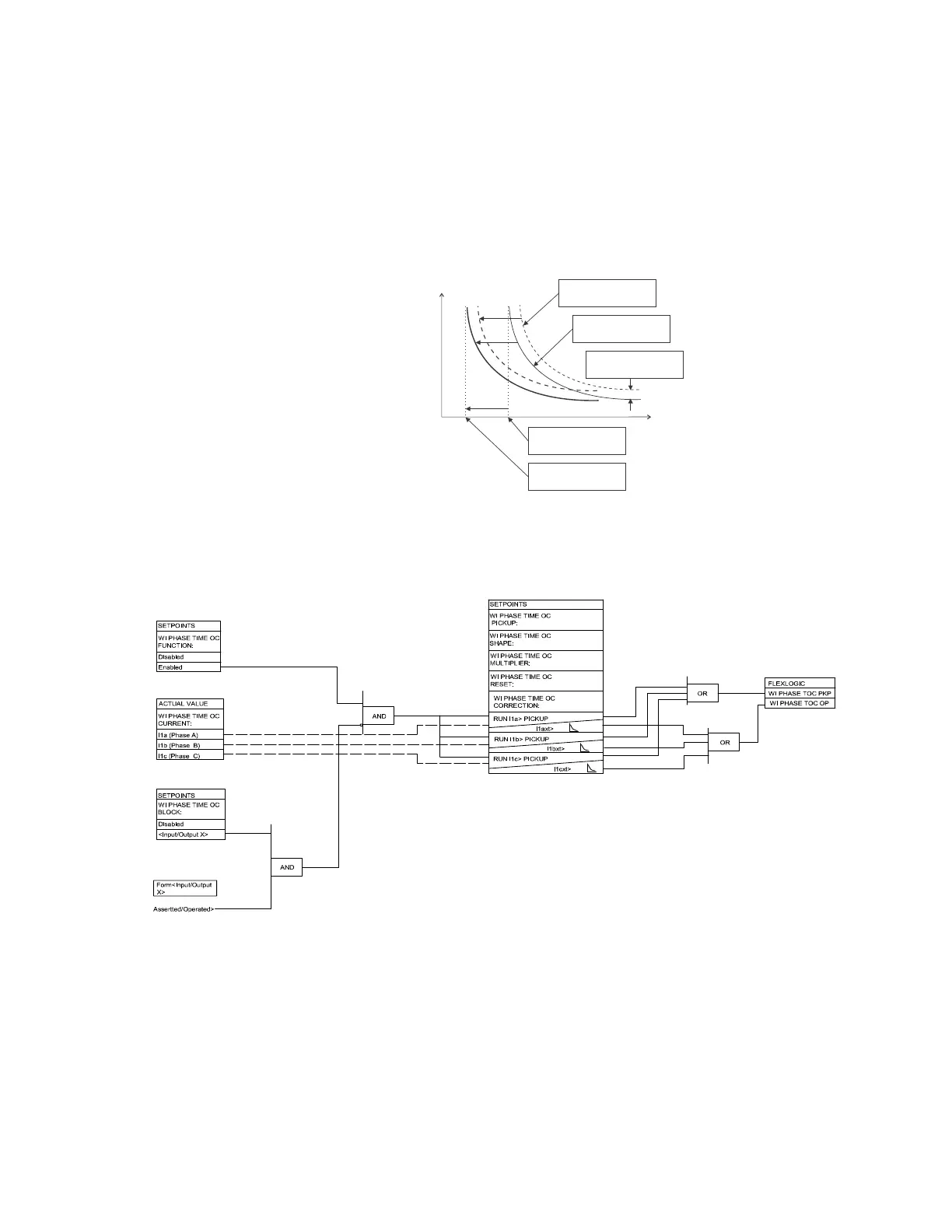
• W1(3) HARMONIC DERATING CORRECTION: Select “Enabled” to enable automatic
harmonic derating correction of the winding 1(3) phase time overcurrent curve. The
745 calculates the derated transformer capability when supplying non-sinusoidal
load currents (as per ANSI / IEEE C57.110-1986) and, when this feature is enabled,
automatically shifts the phase time overcurrent curve pickup in order to maintain the
required protection margin with respect to the transformer thermal damage curve, as
illustrated below.
FIGURE 5–15: Harmonic derating correction
FIGURE 5–16: Phase time overcurrent scheme logic
current
time
Transformer thermal
damagecurve
Selected relay time
overcurrent curve
Pickup setting based
rated load capability
Pickup shifted based
on harmonicderating
Transformer thermal
protection margin