CHAPTER 5: SETPOINTS S4 ELEMENTS
745 TRANSFORMER PROTECTION SYSTEM – INSTRUCTION MANUAL 5–65
5.6.5.4 Winding 1 to 3 Phase Instantaneous Overcurrent
PATH: SETPOINTS S4 ELEMENTS PHASE OC W1(3) PHASE INST OC 1(2)
• W1(3) PHASE INST OC 1(2) PICKUP: Enter the level of phase current (in units of relay
nominal current) above which the winding 1(3) phase instantaneous overcurrent 1
element will pickup and start the delay timer.
• W1(3) PHASE INST OC 1(2) DELAY: Enter the time that the phase current must remain
above the pickup level before the element operates.
Note
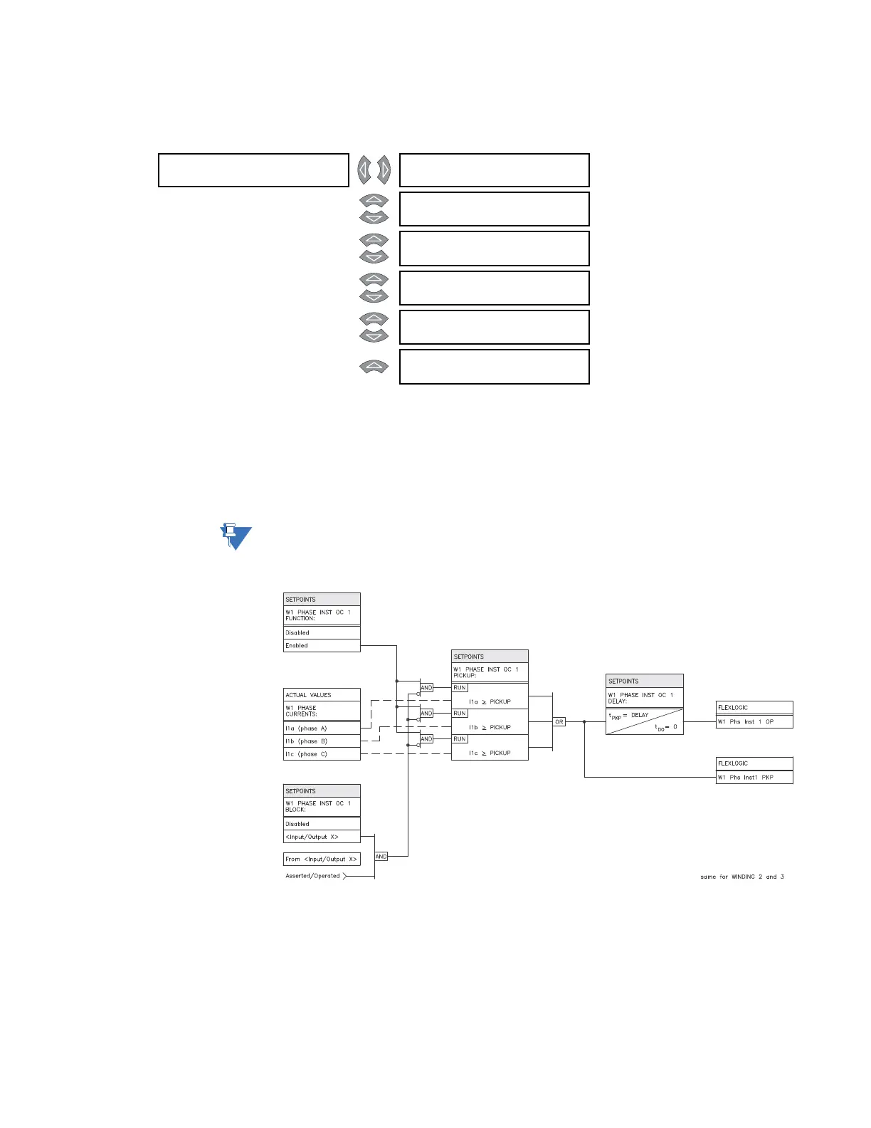
The setpoint messages above and the following logic diagram are identical for the
phase instantaneous overcurrent 2 element.
FIGURE 5–17: Phase instantaneous overcurrent 1 scheme logic
W1 PHASE []
INST OC 1
W1 PHASE INST OC 1
FUNCTION: Enabled
Range: Enabled, Disabled
MESSAGE
W1 PHASE INST OC 1
RLYS (1-8): --------
Range: 1 to 8
MESSAGE
W1 PHASE INST OC 1
TARGET: Latched
Range: Self-Reset, Latched, None
MESSAGE
W1 PHASE INST OC 1
PICKUP: 10.00 x CT
Range: 0.05 to 20.00 x CT in steps of
0.01
MESSAGE
W1 PHASE INST OC 1
DE L AY: 0 ms
Range: 0 to 60000 ms in steps of 1
MESSAGE
W1 PHASE INST OC 1
BLOCK: Disabled
Range: Logc Inpt 1 to 16, Virt Inpt 1 to
16, Output Rly 2 to 8, SelfTest
Rly, Vir Outpt 1 to 5, Disabled