5–66 745 TRANSFORMER PROTECTION SYSTEM – INSTRUCTION MANUAL
S4 ELEMENTS CHAPTER 5: SETPOINTS
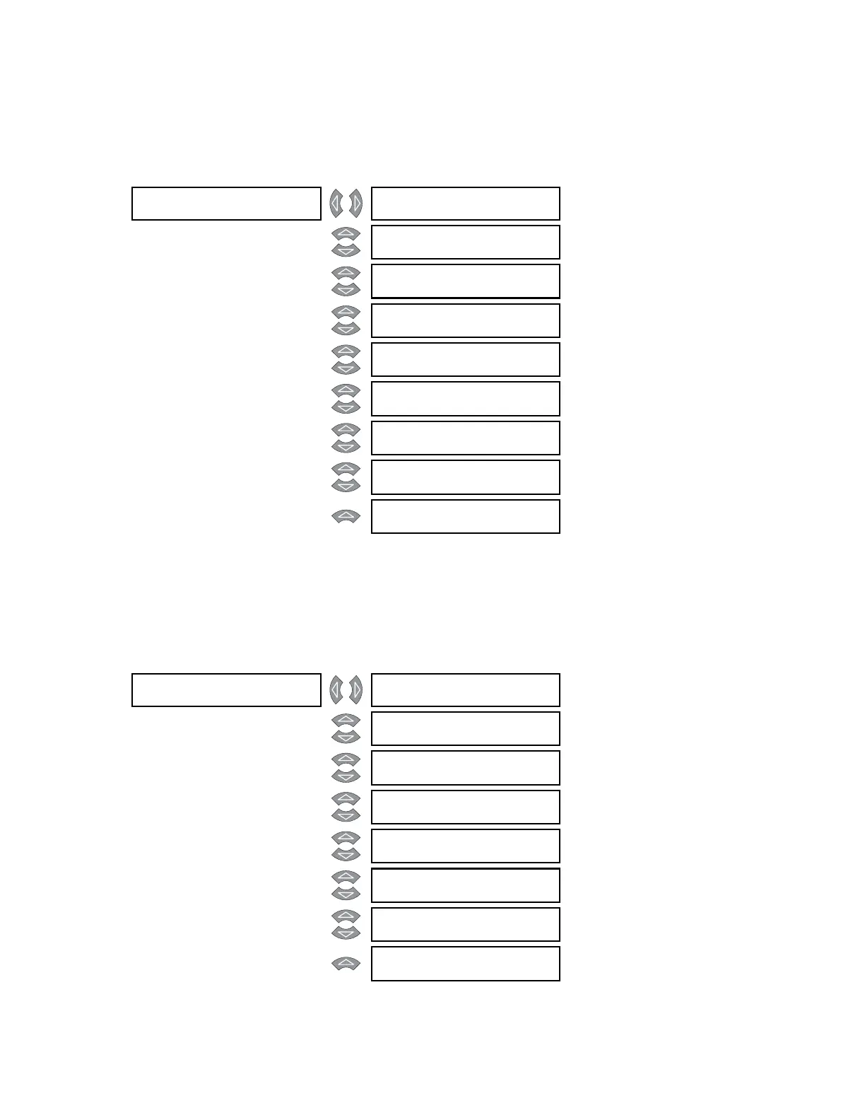
5.6.6 Neutral overcurrent
5.6.6.1 Main menu
PATH: SETPOINTS S4 ELEMENTS NEUTRAL OC
In the 745, “neutral” refers to residual current (3I
0
), calculated internally as the vector sum
of the three phases. The relay includes neutral time overcurrent and two levels of neutral
instantaneous overcurrent for each winding.
5.6.6.2 Neutral Time Overcurrent
PATH: SETPOINTS S4 ELEMENTS NEUTRAL OC W1(3) NTRL TIME OC
NEUTRAL OC [] W1 NTRL []
TIME OC
See page 5–66
MESSAGE
W2 NTRL []
TIME OC
See page 5–66
MESSAGE
W3 NTRL []
TIME OC
See page 5–66
MESSAGE
W1 NTRL []
INST OC 1
See page 5–68
MESSAGE
W2 NTRL []
INST OC 1
See page 5–68
MESSAGE
W3 NTRL []
INST OC 1
See page 5–68
MESSAGE
W1 NTRL []
INST OC 2
See page 5–68
MESSAGE
W2 NTRL []
INST OC 2
See page 5–68
MESSAGE
W3 NTRL []
INST OC 2
See page 5–68
W1 NTRL []
TIME OC
W1 NEUTRAL TIME OC
FUNCTION: Enabled
Range: Enabled, Disabled
MESSAGE
W1 NEUTRAL TIME OC
RLYS (1-8): --------
Range: 1 to 8
MESSAGE
W1 NEUTRAL TIME OC
TARGET: Latched
Range: Self-Reset, Latched, None
MESSAGE
W1 NEUTRAL TIME OC
PICKUP: 0.85 x CT
Range: 0.05 to 20.00 x CT in steps of
0.01
MESSAGE
W1 NEUTRAL TIME OC
SHAPE: Ext Inverse
Range: see description below
MESSAGE
W1 NEUTRAL TIME OC
MULTIPLIER: 1.00
Range: 0.00 to 100.00 in steps of 0.01
MESSAGE
W1 NEUTRAL TIME OC
RESET: Linear
Range: Instantaneous, Linear
MESSAGE
W1 NEUTRAL TIME OC
BLOCK: Disabled
Range: Logc Inpt 1 to 16, Virt Inpt 1 to
16, Output Rly 2 to 8, SelfTest
Rly, Vir Outpt 1 to 5, Disabled