CHAPTER 5: SETPOINTS S4 ELEMENTS
745 TRANSFORMER PROTECTION SYSTEM – INSTRUCTION MANUAL 5–71
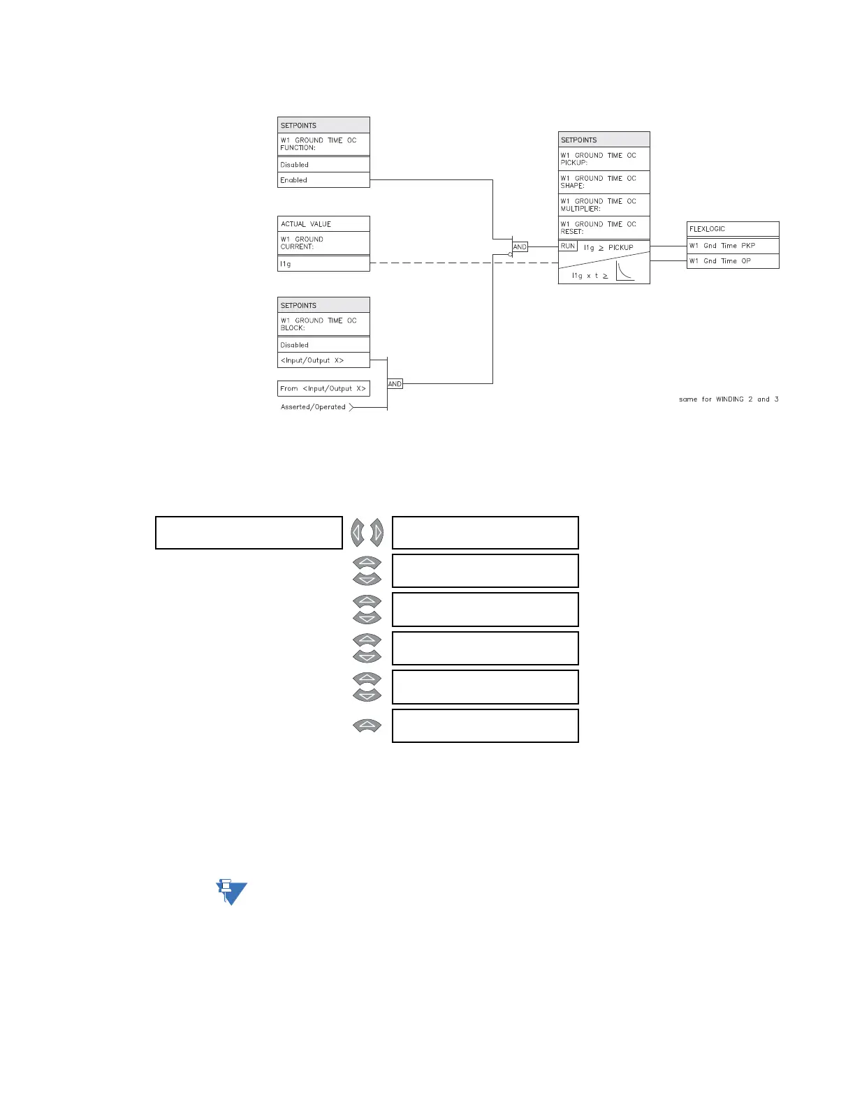
FIGURE 5–20: Ground time overcurrent scheme logic
5.6.7.3 Ground Instantaneous Overcurrent
PATH: SETPOINTS S4 ELEMENTS GROUND OC W1(3) GROUND INST OC 1(2)
• W1(3) GROUND INST OC 1(2) PICKUP: Enter the level of ground current (in units of
relay nominal current) above which the winding 1(3) ground instantaneous
overcurrent 1 element will pickup and start the delay timer.
• W1(3) GROUND INST OC 1(2) DELAY: Enter the time that the ground current must
remain above the pickup level before the element operates.
Note
The messages above and scheme logic below are identical for windings 2 and 3 of
ground instantaneous overcurrent 1 and all windings on the ground instantaneous
overcurrent 2 element.
W1 GND []
INST OC 1
W1 GROUND INST OC 1
FUNCTION: Disabled
Range: Enabled, Disabled
MESSAGE
W1 GROUND INST OC 1
RLYS (1-8): --------
Range: 1 to 8
MESSAGE
W1 GROUND INST OC 1
TARGET: Latched
Range: Self-Reset, Latched, None
MESSAGE
W1 GROUND INST OC 1
PICKUP: 10.00 x CT
Range: 0.05 to 20.00 x CT in steps of
0.01
MESSAGE
W1 GROUND INST OC 1
DE L AY: 0 ms
Range: 0 to 60000 ms in steps of 1
MESSAGE
W1 GROUND INST OC 1
BLOCK: Disabled
Range: Logc Inpt 1 to 16, Virt Inpt 1 to
16, Output Rly 2 to 8, SelfTest
Rly, Vir Outpt 1 to 5, Disabled