5–74 745 TRANSFORMER PROTECTION SYSTEM – INSTRUCTION MANUAL
S4 ELEMENTS CHAPTER 5: SETPOINTS
FIGURE 5–25: RGF and percent differential zones of protection
The 745 implementation of restricted ground fault (shown below) is a low impedance
current differential scheme where “spill” current due to CT tolerances is handled via load
bias similar to the percent differential. The 745 calculates the vectorial difference of the
residual and ground currents (i.e. 3I
0
- I
g
) and divides this by the maximum line current
(I
max
) to produce a percent slope value. The slope setting allows the user to determine the
sensitivity of the element based on the class and quality of the CTs used. Typically no more
than 4% overall error due to CT “spill” is assumed for protection class CTs at nominal load.
Note
The restricted ground fault protection is also available for delta windings with ground
inputs as shown in table 3.2.
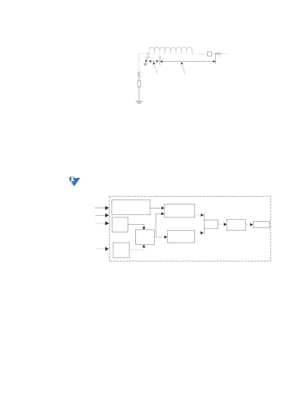
FIGURE 5–26: Restricted ground fault implementation
The issue of maloperation due to heavy external faults resulting in CT saturation is handled
by a programmable timer. The timer provides the necessary delay for the external fault to
be cleared by the appropriate external protection with the added benefit that if the RGF
element remains picked up after the timer expires, the 745 operates and clears the fault.
This approach provides backup protection. Since the restricted ground fault element is
targeted at detecting low magnitude internal winding fault currents, the time delay for
internal faults is of little consequence, since sensitivity and security are the critical
parameters.
For example, consider a transformer with the following specifications:
Rg
35%
RGF
ZONE
DIFFERENTIAL
ZONE
WINDING
Ia
Ib
Ic
Ig
Timer
0to0.5 s
OUTPUT
Calculate
Maximum Phase
Current
Slope =Igd/Imax
Slope >Setpoint
Imax
Igd >Setpoint
AND
Calculate
3I
0
Calculate
|3I – Ig|
0
Measure
Ig
Igd
745 RELAY