CHAPTER 5: SETPOINTS S4 ELEMENTS
745 TRANSFORMER PROTECTION SYSTEM – INSTRUCTION MANUAL 5–73
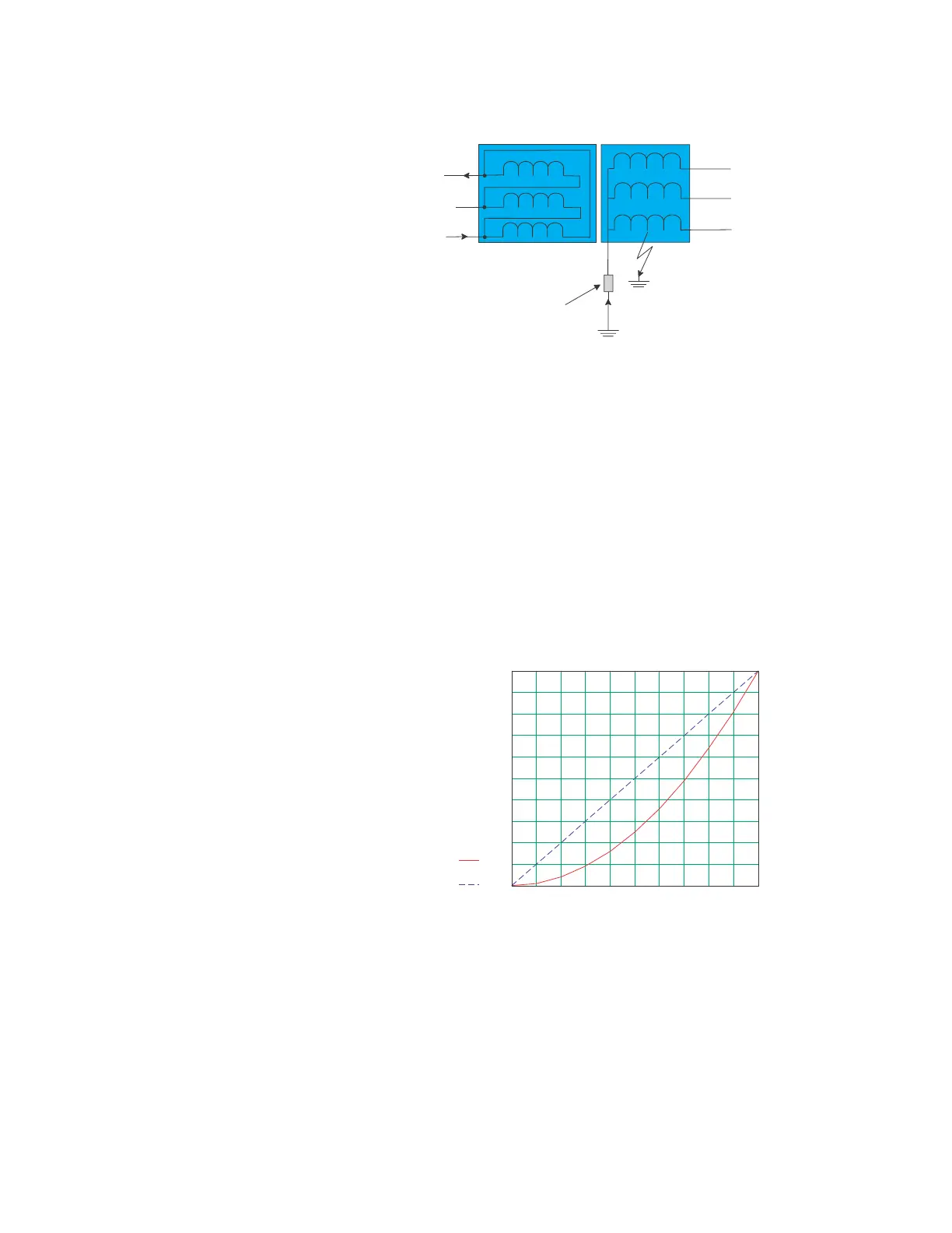
FIGURE 5–23: Resistance grounded wye wiring
An internal ground fault on an impedance grounded wye winding (see second figure
above) produces a fault current (I
F
) dependent on the value of the ground impedance and
the position of the fault on the winding with respect to the neutral point. The resultant
primary current (I
P
) will be negligible for faults on the lower 30% of the winding since the
fault voltage will not be the system voltage but the result of the transformation ratio
between the primary windings and the percentage of shorted turns on the secondary.
Therefore, the resultant differential currents could be below the slope threshold of the
percent differential element and thus the fault could go undetected. The graph below
shows the relationship between the primary (I
P
) and fault (I
F
) currents as a function of the
distance of the fault point from the neutral and FIGURE 5–25: RGF and percent differential
zones of protection outlines the zones of effective protection along the winding for an
impedance grounded wye.
FIGURE 5–24: Fault currents vs. points from neutral
WyeWinding
FAULT
IF
Delta Winding
IP
Impedance grounded
wye winding
0 10 20 30 40 50 60 70 80 90 100
0
10
20
30
40
50
60
70
80
90
100
Ip(x)
Ifault(x)
% MaxIfault
Ifault
Ip
x=distance offault from neutral
 Loading...


