CHAPTER 5: SETPOINTS S4 ELEMENTS
745 TRANSFORMER PROTECTION SYSTEM – INSTRUCTION MANUAL 5–77
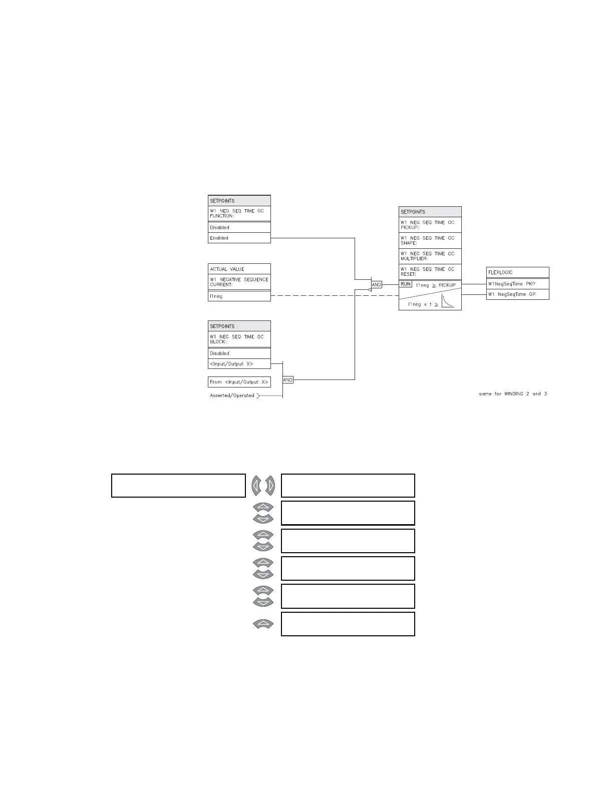
• W1 (3) NEG SEQ TIME OC MULTIPLIER: Enter the multiplier constant by which the
selected time overcurrent curve shape (the base curve) is to be shifted in time.
• W1 (3) NEG SEQ TIME OC RESET: Select the “Linear” reset to coordinate with
electromechanical time overcurrent relays, in which the reset characteristic (when the
current falls below the reset threshold before tripping) is proportional to ratio of
“energy” accumulated to that required to trip. Select the “Instantaneous” reset to
coordinate with relays, such as most static units, with instantaneous reset
characteristics.
FIGURE 5–28: Negative sequence time overcurrent scheme logic
5.6.9.3 Negative Sequence Instantaneous Overcurrent
PATH: SETPOINTS S4 ELEMENTS NEG SEQ OC W1(3) NEG SEQ INST OC
• W1(3) NEG SEQ INST OC PICKUP: Enter the level of negative sequence current (in units
of relay nominal current) above which the winding 1(3) negative sequence
instantaneous overcurrent element will pickup and start the delay timer.
• W1(3) NEG SEQ INST OC DELAY: Enter the time that the negative sequence current
must remain above the pickup level before the element operates.
W1 NEG SEQ []
INST OC
W1 NEG SEQ INST OC
FUNCTION: Disabled
Range: Enabled, Disabled
MESSAGE
W1 NEG SEQ INST OC
RLYS (1-8): --------
Range: 1 to 8
MESSAGE
W1 NEG SEQ INST OC
TARGET: Latched
Range: Self-Reset, Latched, None
MESSAGE
W1 NEG SEQ INST OC
PICKUP: 10.00 x CT
Range: 0.05 to 20.00 x CT in steps of
0.01
MESSAGE
W1 NEG SEQ INST OC
DE L AY: 0 ms
Range: 0 to 60000 ms in steps of 1
MESSAGE
W1 NEG SEQ INST OC
BLOCK: Disabled
Range: Logc Inpt 1 to 16, Virt Inpt 1 to
16, Output Rly 2 to 8, SelfTest
Rly, Vir Outpt 1 to 5, Disabled