CHAPTER 5: SETPOINTS S4 ELEMENTS
745 TRANSFORMER PROTECTION SYSTEM – INSTRUCTION MANUAL 5–79
Note
We strongly recommend the use of either the voltage, current, or both, signals for
supervision. If no supervising conditions are enabled, the element could produce
undesirable operation!
5.6.10.2 Underfrequency
PATH: SETPOINTS S4 ELEMENTS FREQUENCY UNDERFREQUENCY 1(2)
• MINIMUM OPERATING CURRENT: Enter the minimum value of winding 1 phase A
current (in units of relay nominal current) required to allow the underfrequency
element to operate.
• MINIMUM OPERATING VOLTAGE: Enter the minimum value of voltage (in units of relay
nominal voltage) required to allow the underfrequency element to operate.
• UNDERFREQUENCY 1(2) PICKUP: Enter the frequency (in Hz) below which the
underfrequency 1 element will pickup and start the delay timer.
• UNDERFREQUENCY 1(2) DELAY: Enter the time the frequency remains below the
pickup level before element operation.
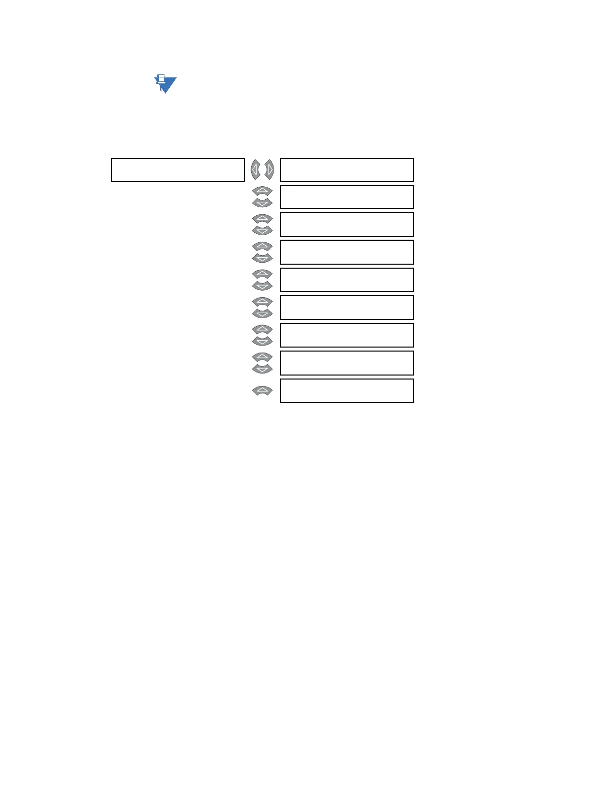
UNDERFREQUENCY []
1
UNDERFREQUENCY 1
FUNCTION: Disabled
Range: Enabled, Disabled
MESSAGE
UNDERFREQUENCY 1
RLYS (1-8): --------
Range: 1 to 8
MESSAGE
UNDERFREQUENCY 1
TARGET: Self-Reset
Range: Self-Reset, Latched, None
MESSAGE
CURRENT SENSING:
Enabled
Range: Enabled, Disabled
MESSAGE
MINIMUM OPERATING
CURRENT: 0.20 x CT
Range: 0.05 to 1.00 x CT in steps of
0.01
MESSAGE
MINIMUM OPERATING
VOLTAGE: 0.50 x VT
Range: 0.10 to 0.99 x CT in steps of
0.01
MESSAGE
UNDERFREQUENCY 1
PICKUP: 59.00 Hz
Range: 45.00 to 59.99 Hz in steps of
0.01
MESSAGE
UNDERFREQUENCY 1
DELAY: 1.00 s
Range: 0.00 to 600.00 s in steps of 0.01
MESSAGE
UNDERFREQUENCY 1
BLOCK: Disabled
Range: Logc Inpt 1 to 16, Virt Inpt 1 to
16, Output Rly 2 to 8, SelfTest
Rly, Vir Outpt 1 to 5, Disabled