5–88 745 TRANSFORMER PROTECTION SYSTEM – INSTRUCTION MANUAL
S4 ELEMENTS CHAPTER 5: SETPOINTS
5.6.12 Harmonics
5.6.12.1 Main Menu
PATH: SETPOINTS S4 ELEMENTS HARMONICS
This section contains the settings to configure the total harmonic distortion monitoring
elements. Included are a THD level element for each winding and each phase.
5.6.12.2 THD Level
PATH: SETPOINTS S4 ELEMENTS HARMONICS W1(3) THD LEVEL
• MINIMUM OPERATING CURRENT: Enter the minimum value of current (in units of relay
nominal current) required to allow the THD level element to operate.
• W1(3) THD PICKUP LEVEL: Enter the total harmonic distortion (in %ƒ
0
) above which
the winding 1(3) total harmonic distortion element level will pickup and start the delay
timer.
• W1(3) THD LEVEL DELAY: Enter the time that the total harmonic distortion must
remain above the pickup level before the element operates.
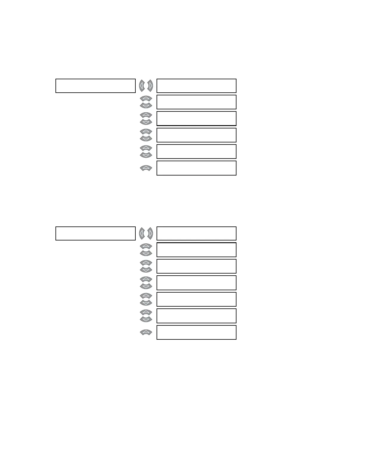
HARMONICS [] W1 THD LEVEL []
See page 5–88
MESSAGE
W2 THD LEVEL []
See page 5–88
MESSAGE
W3 THD LEVEL []
See page 5–88
MESSAGE
W1 HARMONIC []
DERATING
See page 5–89
MESSAGE
W2 HARMONIC []
DERATING
See page 5–89
MESSAGE
W3 HARMONIC []
DERATING
See page 5–89
W1 THD LEVEL [] W1 THD LEVEL
FUNCTION: Disabled
Range: Enabled, Disabled
MESSAGE
W1 THD LEVEL
RLYS (1-8): --------
Range: 1 to 8
MESSAGE
W1 THD LEVEL
TARGET: Self-Reset
Range: Self-Reset, Latched, None
MESSAGE
MINIMUM OPERATING
CURRENT: 0.10 x CT
Range: 0.03 to 1.00 x CT in steps of
0.01
MESSAGE
W1 THD LEVEL
PICKUP: 50.0% f0
Range: 0.1 to 50.0% f
0
in steps of 0.1
MESSAGE
W1 THD LEVEL
DE L AY: 1 0 s
Range: 0 to 60000 s in steps of 1
MESSAGE
W1 THD LEVEL
BLOCK: Disabled
Range: Logc Inpt 1 to 16, Virt Inpt 1 to
16, Output Rly 2 to 8, SelfTest
Rly, Vir Outpt 1 to 5, Disabled
 Loading...


