CHAPTER 5: SETPOINTS S4 ELEMENTS
745 TRANSFORMER PROTECTION SYSTEM – INSTRUCTION MANUAL 5–91
Three protection elements are provided as part of the Loss of Life feature. The first element
monitors the hottest-spot temperature. The second element monitors the aging factor and
the third monitors the total accumulated loss of life. Each element produces an output
when the monitored quantity exceeds a set limit.
The insulation aging / loss of life feature is a field-upgradable feature. For the feature (and
associated elements) to operate correctly, it must first be enabled under the factory
settings using the passcode provided at purchase. If the feature was ordered when the
relay was purchased, then it is already enabled. Note that setting this feature using the
EnerVista 745 Setup software requires that it be enabled the under File > Properties > Loss
of Life menu. If the computer is communicating with a relay with the feature installed, it is
automatically detected.
For the computations to be performed correctly, it is necessary to enter the transformer
data under
S2 SYSTEM SETUP TRANSFORMER. The transformer load is taken from the
winding experiencing the greatest loading. All transformer and winding setpoints must be
correct or the computations will be meaningless.
The preferred approach for ambient temperature is to use an RTD connected to the 745. If
this is not feasible, average values for each month of the year can be entered as settings,
under
S2 SYSTEM SETUP AMBIENT TEMPERATURE AMBIENT RTD TYPE and selecting
“By Monthly Average”.
5.6.13.2 Hottest Spot Limit
PATH: SETPOINTS S4 ELEMENTS INSULATION AGING HOTTEST-SPOT LIMIT
The hottest-spot limit element provides a means of detecting an abnormal hot spot inside
the transformer. The element operates on the computed hottest-spot value. The hottest-
spot temperature will revert to 0°C for 1 minute if the power supply to the relay is
interrupted.
• HOTTEST SPOT LIMIT PICKUP: Enter the hottest-spot temperature required for
operation of the element. This setting should be a few degrees above the maximum
permissible hottest-spot temperature under emergency loading condition and
maximum ambient temperature.
• HOTTEST SPOT LIMIT DELAY: Enter a time delay above which the hottest-spot
temperature must remain before the element operates.
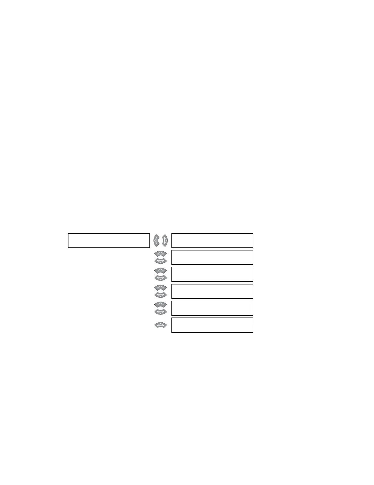
HOTTEST-SPOT []
LIMIT
HOTTEST-SPOT LIMIT
FUNCTION: Disabled
Range: Enabled, Disabled
MESSAGE
HOTTEST-SPOT LIMIT
RLYS (1-8): --------
Range: 1 to 8
MESSAGE
HOTTEST-SPOT LIMIT
TARGET: Self-Reset
Range: Self-Reset, Latched, None
MESSAGE
HOTTEST-SPOT LIMIT
PICKUP: 150°C
Range: 50 to 300°C in steps of 1
MESSAGE
HOTTEST-SPOT LIMIT
DE L AY: 1 0 min
Range: 0 to 60000 min. in steps of 1
MESSAGE
HOTTEST-SPOT LIMIT
BLOCK: Disabled
Range: Logc Inpt 1 to 16, Virt Inpt 1 to
16, Output Rly 2 to 8, SelfTest
Rly, Vir Outpt 1 to 5, Disabled