5–96 745 TRANSFORMER PROTECTION SYSTEM – INSTRUCTION MANUAL
S4 ELEMENTS CHAPTER 5: SETPOINTS
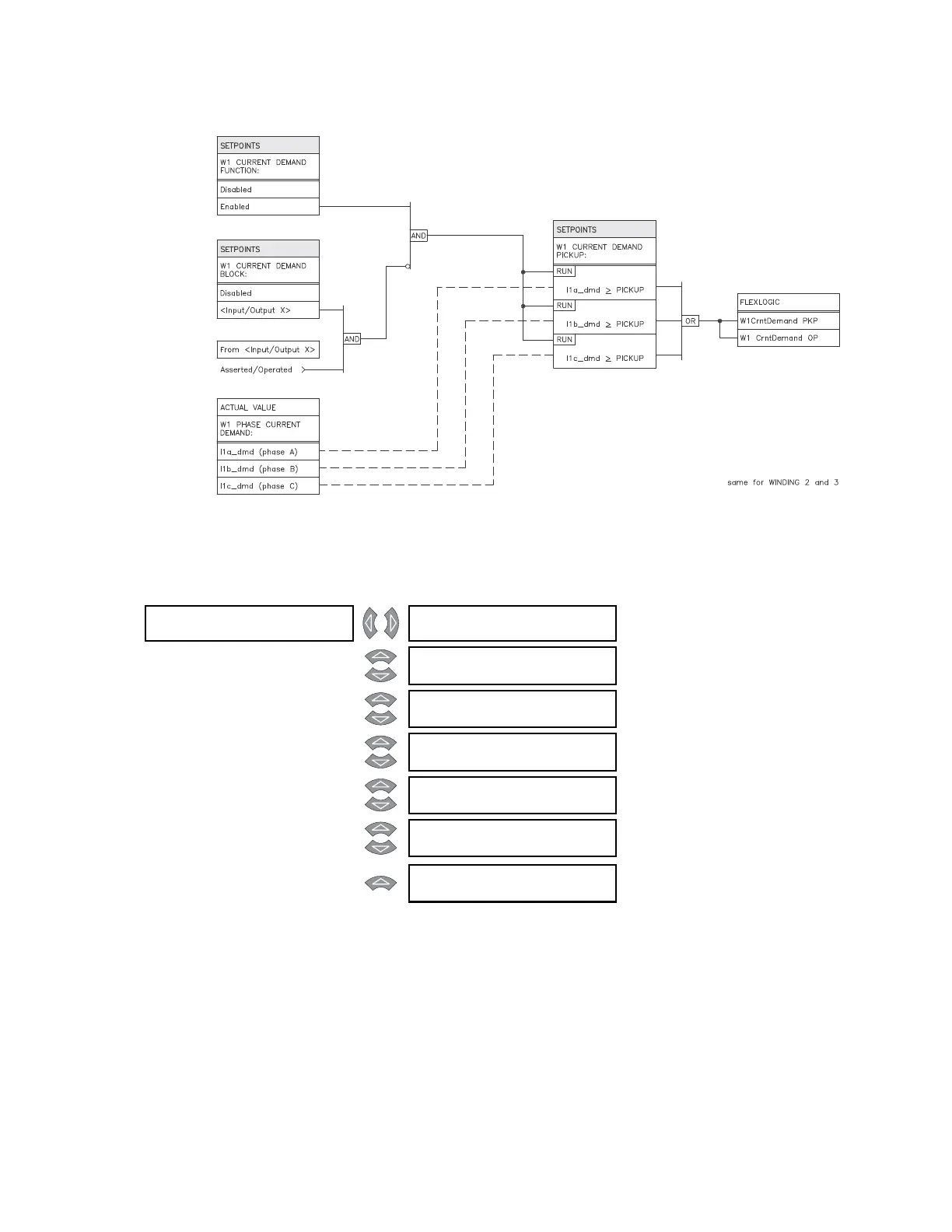
FIGURE 5–44: Current demand scheme logic
5.6.16 Transformer Overload
PATH: SETPOINTS S4 ELEMENTS XFORMER OVERLOAD
• TRANSFORMER OVERLOAD PICKUP: This setting identifies the level of transformer
overload, where the pickup delay starts timing. The setting is expressed as a
percentage of the transformer base MVA rating, and is normally set at or above the
maximum rated MVA from the transformer nameplate.
• XFMR OVERTEMP ALARM SIGNAL: Select any logic input that, when asserted,
indicates the transformer cooling system has failed and an over-temperature
condition exists. The logic input should be connected to the transformer winding
temperature alarm contacts.
XFORMER []
OVERLOAD
TRANSFORMER OVERLOAD
FUNCTION: Disabled
Range: Enabled, Disabled
MESSAGE
TRANSFORMER OVERLOAD
RLYS (1-8): --------
Range: 1 to 8
MESSAGE
TRANSFORMER OVERLOAD
TARGET: Self-Reset
Range: Self-Reset, Latched, None
MESSAGE
TRANSFORMER OVERLOAD
PICKUP: 208% rated
Range: 50 to 300% of Rated Load in
steps of 1
MESSAGE
TRANSFORMER OVERLOAD
DE L AY: 1 0 s
Range: 0 to 60000 s in steps of 1
MESSAGE
TRANSFORMER OVERLOAD
BLOCK: Disabled
Range: Logc Inpt 1 to 16, Virt Inpt 1 to
16, Output Rly 2 to 8, SelfTest
Rly, Vir Outpt 1 to 5, Disabled
MESSAGE
XFMR OVERTEMP ALARM
SIGNAL: Disabled
Range: Disabled, Logc Inpt 1 to 16