CHAPTER 5: SETPOINTS S4 ELEMENTS
745 TRANSFORMER PROTECTION SYSTEM – INSTRUCTION MANUAL 5–97
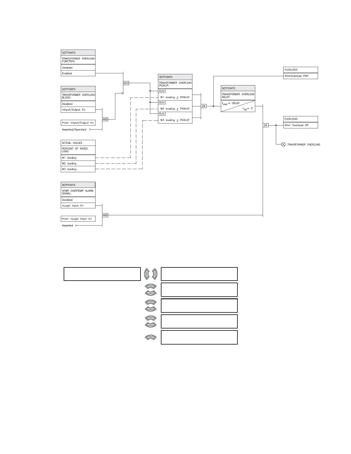
FIGURE 5–45: Transformer overload scheme logic
5.6.17 Tap Changer Failure
PATH: SETPOINTS S4 ELEMENTS TAP CHANGR FAILURE
The tap changer failure element monitors the resistance seen by the tap changer
monitoring circuit. The element produces an output signal when the tap changer position
exceeds the maximum number of taps (set by the
NUMBER OF TAP POSITIONS setpoint) by
two. This signal can be used as an alarm or as a signal to change the setpoint group. A
change in the setpoint group would be programmed through the FlexLogic™. This
approach would be useful if very sensitive settings had been used in the normal in-service
setpoint group for the harmonic restrained differential element, assuming that the tap
changer position was used to compensate the input current magnitude.
TAP CHA NGR []
FAILURE
TAP CHANGER FAILURE
FUNCTION: Disabled
Range: Enabled, Disabled
MESSAGE
TAP CHANGER FAILURE
RLYS (1-8): --------
Range: 1 to 8
MESSAGE
TAP CHANGER FAILURE
TARGET: Self-Reset
Range: Self-Reset, Latched, None
MESSAGE
TAP CHANGER FAILURE
DELAY: 5.00 s
Range: 0.00 to 600.00 s in steps of 0.01
MESSAGE
TAP CHANGER FAILURE
BLOCK: Disabled
Range: Logc Inpt 1 to 16, Virt Inpt 1 to
16, Output Rly 2 to 8, SelfTest
Rly, Vir Outpt 1 to 5, Disabled