CHAPTER 5: SETPOINTS S5 OUTPUTS
745 TRANSFORMER PROTECTION SYSTEM – INSTRUCTION MANUAL 5–101
2. Gates have only one output.
3. The output of a gate can be the input to another gate. Therefore, according to rule 1,
the former gate will precede the latter gate in the equation.
4. Any input can be used more than once in an equation.
5. The output of an equation can be used as an input to any equation (including
feedback to itself).
6. If all parameters of an equation are not used, the ‘END’ parameter must follow the last
parameter used.
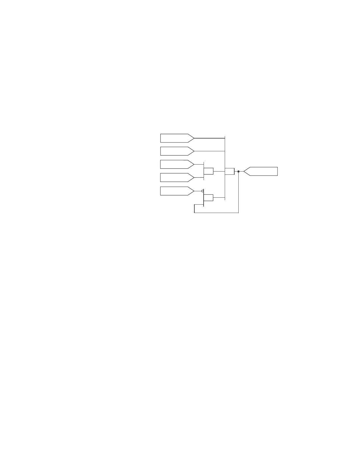
As an example, assume that the following logic is required to operate output relay 2:
FIGURE 5–47: FlexLogic™ example
Based on the rules given above, the output relay 2 FlexLogic™ equation is shown above.
On the left is a stack of boxes showing the FlexLogic™ messages for output relay 2. On the
right of the stack of boxes is an illustration of how the equation is interpreted.
In this example, the inputs of the four-input OR gate are Percent Diff OP, Inst Diff OP, the
output of the XOR gate, and the output of the AND gate. The inputs of the two-input AND
gate are the output of the NOT gate, and Output Relay 2. The input to the NOT gate is Logic
Input 2. The inputs to the two-input XOR gate are Virtual Output 1 and Logic Input 1. For all
these gates, the inputs precede the gate itself.
This ordering of parameters of an equation, where the gate (or “operator”) follows the input
(or “value”) is commonly referred to as “postfix” or “Reverse Polish” notation.
Percent Diff
OPERATE
Inst Diff
OPERATE
Virtual Output 1
OPERATE
AND
XOR
Logic Input 2
ASSERTED
Logic Input 1
ASSERTED
OR
Output Relay 2
OPERATE