5–102 745 TRANSFORMER PROTECTION SYSTEM – INSTRUCTION MANUAL
S5 OUTPUTS CHAPTER 5: SETPOINTS
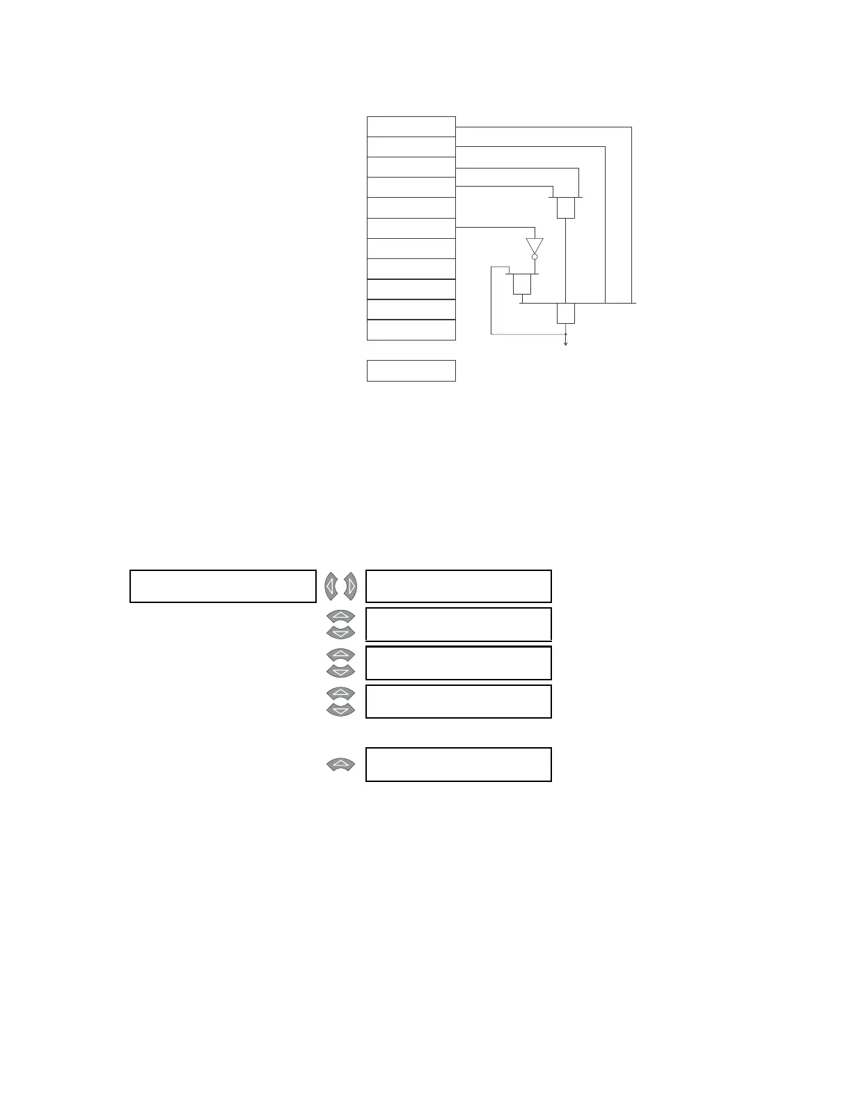
FIGURE 5–48: FlexLogic™ example implemented
Any equation entered in the 745 that does not make logical sense according to the
notation described here, will be flagged as a self-test error. The
SELF TEST ERROR: FlexLogic
Eqn
message will be displayed until the error is corrected.
5.7.5 Output Relays
PATH: SETPOINTS S5 OUTPUTS OUTPUT RELAYS OUTPUT RELAY 1(8)
This section contains the settings (including the FlexLogic™ equation) to configure output
relays 1 to 8.
• OUTPUT 1(8) NAME: Press ENTER edit the name of the output. The text may be
changed from “Solid State Trip” one character at a time, using the VALUE keys. Press
ENTER to store the edit and advance to the next character position.
• OUTPUT 1(8) OPERATION: Select “Latched” to maintain the output 1(8) contacts in the
energized state, even after the condition that caused the contacts to operate is
cleared, until a reset command is issued (or automatically after one week). Select
“Self-reset” to automatically de-energize the contacts after the condition is cleared.
The solid state output (output 1) remains closed until externally reset by a momentary
OUTPUT 2 FLEXLOGIC
O1: Percent Diff OP
OUTPUT 2 FLEXLOGIC
O2: Inst Diff OP
OUTPUT 2 FLEXLOGIC
O3: Virtual Output 1
OUTPUT 2 FLEXLOGIC
O4: Logic Input 1
OUTPUT 2 FLEXLOGIC
O7: NOT
OUTPUT 2 FLEXLOGIC
O5: XOR (2 inputs)
XOR
AND
OR
OUTPUT 2 FLEXLOGIC
O8: Output Relay 2
OUTPUT 2 FLEXLOGIC
O6: Logic Input 2
OUTPUT 2 FLEXLOGIC
O9: AND (2 inputs)
OUTPUT 2 FLEXLOGIC
11: END
Output Relay 2
OPERATE
OUTPUT 2 FLEXLOGIC
1O: OR (4 inputs)
OUTPUT 2 FLEXLOGIC
20: END
...
OUTPUT RELAY 1 [] OUTPUT 1 NAME:
Solid State Trip
Range: 18 alphanumeric characters
MESSAGE
OUTPUT 1 OPERATION:
Self-Resetting
Range: Self-Resetting, Latched
MESSAGE
OUTPUT 1 TYPE:
Trip
Range: Trip, Alarm, Control
MESSAGE
OUTPUT 1 FLEXLOGIC
01: Percent Diff Op
Range: any FlexLogic™ input or gate
↓
MESSAGE
OUTPUT 1 FLEXLOGIC
20: END
Range: any FlexLogic™ input or gate