5–108 745 TRANSFORMER PROTECTION SYSTEM – INSTRUCTION MANUAL
S6 TESTING CHAPTER 5: SETPOINTS
5.8.3 Analog Outputs
PATH: SETPOINTS S6 TESTING ANALOG OUTPUTS
The 745 has the ability to override the normal function of analog transducer outputs,
forcing each to any level of its output range. Enabling this feature turns the Test Mode LED
on and de-energize the self-test relay.
• FORCE ANALOG OUTPUT FUNCTION: Select “Enabled” to enable the analog output
testing and override the analog output normal operation. This setpoint defaults to
“Disabled” at power on.
• FORCE ANALOG OUT 1(7): Enter the percentage of the DC mA output range of analog
output 1(7). For example, if the analog output range has been programmed to 4 to 20
mA, entering 100% outputs 20 mA, 0% outputs 4 mA, and 50% outputs 12 mA. This
setpoint is only operational if analog output testing is enabled.
5.8.4 Simulation
5.8.4.1 Main Menu
PATH: SETPOINTS S4 ELEMENTS INSULATION AGING
5.8.4.2 Simulation Setup
PATH: SETPOINTS S6 TESTING SIMULATION SIMULATION SETUP
The simulation feature allows testing of the functionality of the relay in response to
programmed conditions, without the need of external AC voltage and current inputs.
System parameters such as currents and voltages, phase angles and system frequency
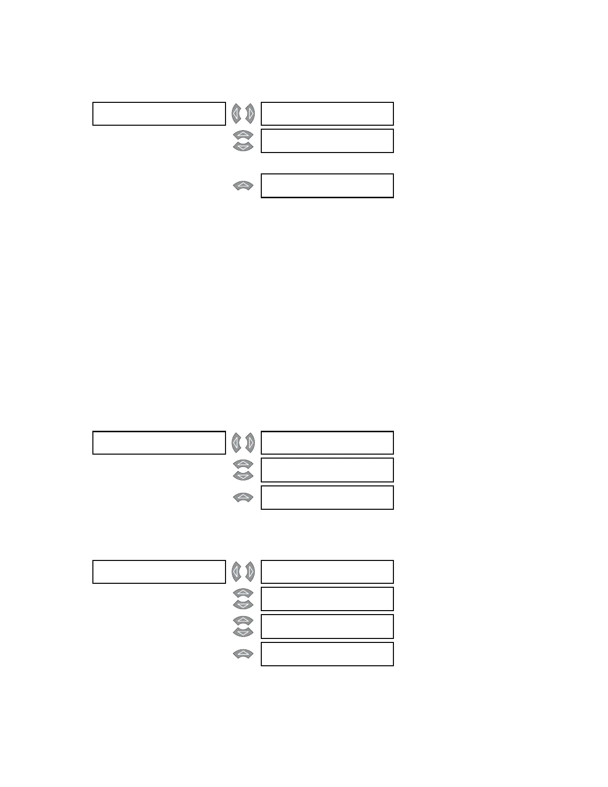
ANALOG OUTPUTS [] FORCE ANALOG OUTPUTS
FUNCTION: Disabled
Range: Enabled, Disabled
MESSAGE
FORCE ANALOG OUT 1:
0%
Range: 0 to 100% in steps of 1
↓
MESSAGE
FORCE ANALOG OUT 7:
0%
Range: 0 to 100% in steps of 1
SIMULATION [] SIMULATION []
SETUP
See below.
MESSAGE
PREFAULT []
VALUES
See page 5–110
MESSAGE
FAULT VALUES []
See page 5–110
SIMULATION []
SETUP
SIMULATION FUNCTION:
Disabled
Range: Disabled, Prefault Mode, Fault
Mode, Playback Mode
MESSAGE
BLOCK OPERATION OF
OUTPUTS: 12345678
Range: Any combination of outputs 1
to 8
MESSAGE
START FAULT MODE
SIGNAL: Disabled
Range: Disabled, Logc Inpt 1 to 16
MESSAGE
START PLAYBACK MODE
SIGNAL: Disabled
Range: Disabled, Logc Inpt 1 to 16