6–10 745 TRANSFORMER PROTECTION SYSTEM – INSTRUCTION MANUAL
A2 METERING CHAPTER 6: ACTUAL VALUES
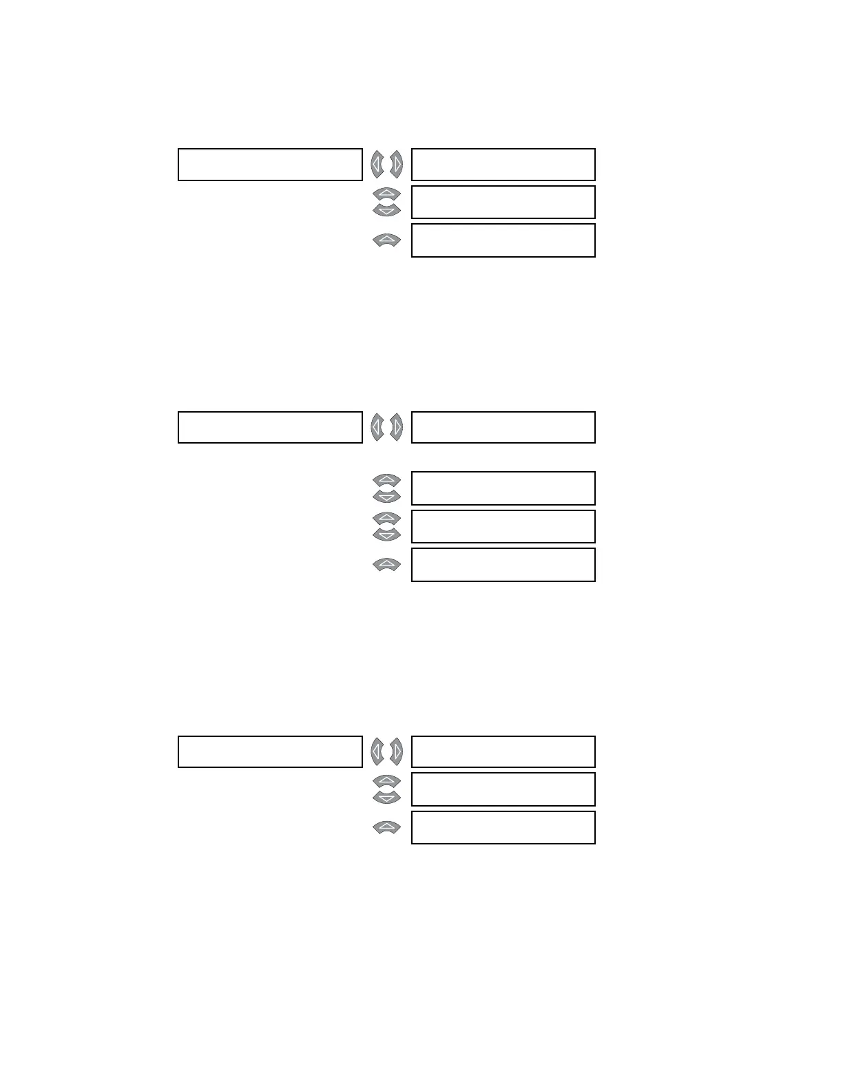
6.3.1.8 Ground Differential Current
PATH: ACTUAL VALUES
A2 METERING CURRENT GROUND DIFFERENTIAL
The ground differential current magnitudes for windings 1 through 3 are shown.
6.3.2 Harmonic Content
6.3.2.1 Main Menu
PATH: ACTUAL VALUES
A2 METERING HARMONIC CONTENT
The 745 can determine the harmonic components of every current that it measures. This
allows it to calculate total harmonic distortion (THD) as well as a harmonic derating factor
that can be used to adjust phase time overcurrent protection to account for additional
internal energy dissipation that arises from the presence of harmonic currents.
6.3.2.2 Harmonic Sub-components
PATH: ACTUAL VALUES
A2 METERING HARMONIC... 2nd(21st) HARMONIC
The 745 is capable of measuring harmonic components up to a frequency of 21 times
nominal system frequency. An actual value is calculated for each phase of each monitored
winding. The example above shows what is displayed in a typical case for harmonic
components (in this case the second harmonic). Similar displays exist for all harmonics up
to the 21
st
.
GROUND []
DIFFERENTIAL
W1 GND DIFFERENTIAL
CURRENT: 0.00 x CT
MESSAGE
W2 GND DIFFERENTIAL
CURRENT: 0.00 x CT
MESSAGE
W3 GND DIFFERENTIAL
CURRENT: 0.00 x CT
HARMONIC []
CONTENT
2nd HARMONIC []
See page 6–10
↓
MESSAGE
21st HARMONIC []
See page 6–10
MESSAGE
THD []
See page 6–11
MESSAGE
HARMONIC []
DERATING
See page 6–11
2nd HARMONIC [] W1 (% f0) H2a: 0.0
H2b: 0.0 H2c: 0.0
MESSAGE
W2 (% f0) H2a: 0.0
H2b: 0.0 H2c: 0.0
MESSAGE
W3 (% f0) H2a: 0.0
H2b: 0.0 H2c: 0.0