CHAPTER 6: ACTUAL VALUES A2 METERING
745 TRANSFORMER PROTECTION SYSTEM – INSTRUCTION MANUAL 6–15
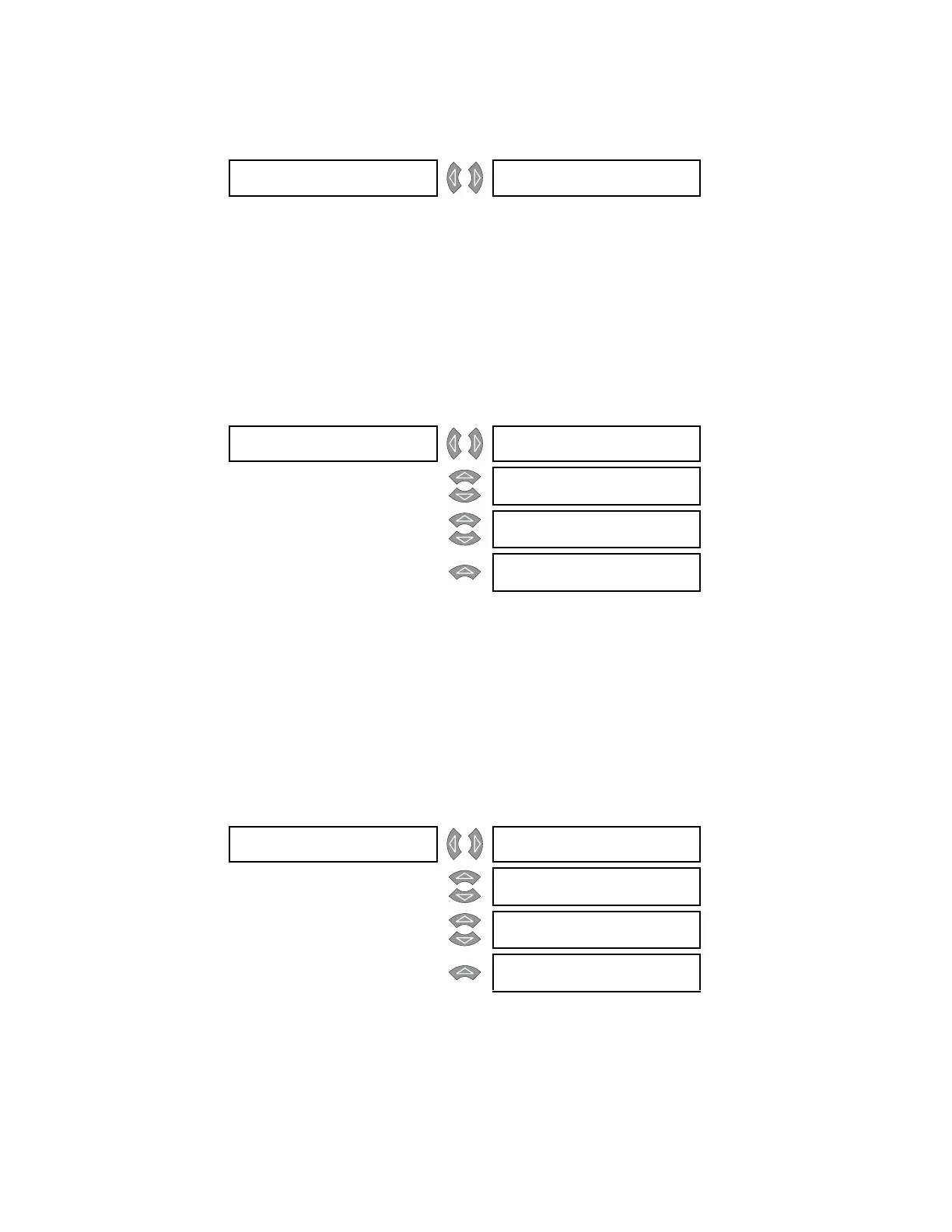
6.3.9 Analog Input
PATH: ACTUAL VALUES A2 METERING ANALOG INPUT
The 745 provides the ability to monitor any external quantity via an auxiliary current input
called the Analog Input. The scaled value of the analog input is shown. In this message, the
name programmed in
S2 SYSTEM SETUP ANALOG INPUT ANALOG INPUT NAME is
displayed instead of ANALOG INPUT (the factory default), and the units programmed in
S2
SYSTEM SETUP
ANALOG INPUT ANALOG INPUT UNITS are displayed instead of “µA”
(which is the factory default).
6.3.10 Power
PATH: ACTUAL VALUES A2 METERING POWER w W1(3) POWER
The 745 calculates and displays real, reactive, and apparent power as well as the power
factor for all of the available windings providing that the voltage sensing is enabled. Power
flowing into the power transformer is designated as source power and power flowing out
of the transformer is designated as load power.
6.3.11 Energy
6.3.11.1 Main Menu
PATH: ACTUAL VALUES
A2 METERING ENERGY
The 745 calculates and displays watthours and varhours for source and load currents for
all available windings, providing that the voltage sensing is enabled.
ANALOG INPUT [] ANALOG INPUT:
0 μA
W1 POWER [] W1 REAL POWER:
0 MW
MESSAGE
W1 REACTIVE POWER:
0 Mvar
MESSAGE
W1 APPARENT POWER:
0 MVA
MESSAGE
W1 POWER FACTOR:
0.00
ENERGY [] ENERGY DATA []
CLEAR
See page 6–16
MESSAGE
W1 ENERGY []
See page 6–16
MESSAGE
W2 ENERGY []
See page 6–16
MESSAGE
W3 ENERGY []
See page 6–16