7–18 745 TRANSFORMER PROTECTION SYSTEM – INSTRUCTION MANUAL
PROTECTION SCHEMES CHAPTER 7: COMMISSIONING
7.5.2.4 Verification of Remote Reset Mode
Set the differential element with a latched target.
Apply enough current to cause the relay to operate, then remove the
current.
The Trip LED and the Phase LED should be latched on.
Set
S1 745 SETUP RESETTING REMOTE RESET SIGNAL to Logic
Input 1(16).
Assert logic input 1.
The target should reset.
7.5.2.5 Verification of Solid-state Output
If the solid-state Output Is Used To Drive Auxiliary Relays,
Verify that these relays operate whenever the relay is in a trip condition.
Ensure that the current though the auxiliary coils is interrupted by an
external contactor between each test.
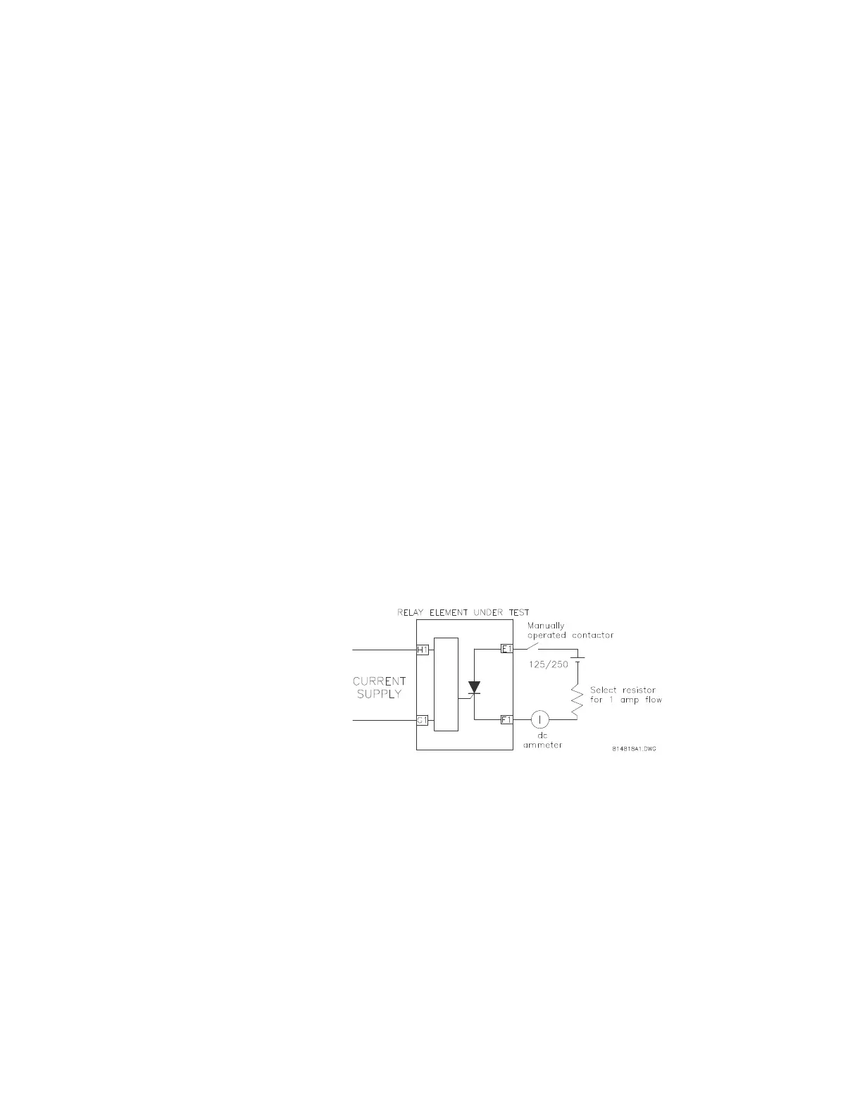
To avoid operating the breaker during the commissioning process when the solid-state
output operates the breaker directly,
Use the circuit shown below to verify this output.
Whenever the relay is in a trip state, current flows through the load
resistor.
Select the resistor for approximately 1 × CT of DC current with the
normal DC supply voltage used in your relay scheme.
FIGURE 7–4: Solid-state output test circuit
7.5.2.6 Basic Operating Time
To measure the basic operating time of the harmonic restrained differential elements,
Connect an AC current signal to terminals H1 and G1, through a
double-pole single-throw switch.
The second pole of the switch starts a timer circuit which is stopped by
the operation of the relay trip contact. Refer to the figure below for
details.
Close the switch and set the current level to three (3) times the minimum
pickup value measured earlier.