CHAPTER 7: COMMISSIONING PROTECTION SCHEMES
745 TRANSFORMER PROTECTION SYSTEM – INSTRUCTION MANUAL 7–19
Re-open the switch and reset all targets on the relay.
Ensure that timer circuit functions correctly.
Close the switch and record operating time of relay.
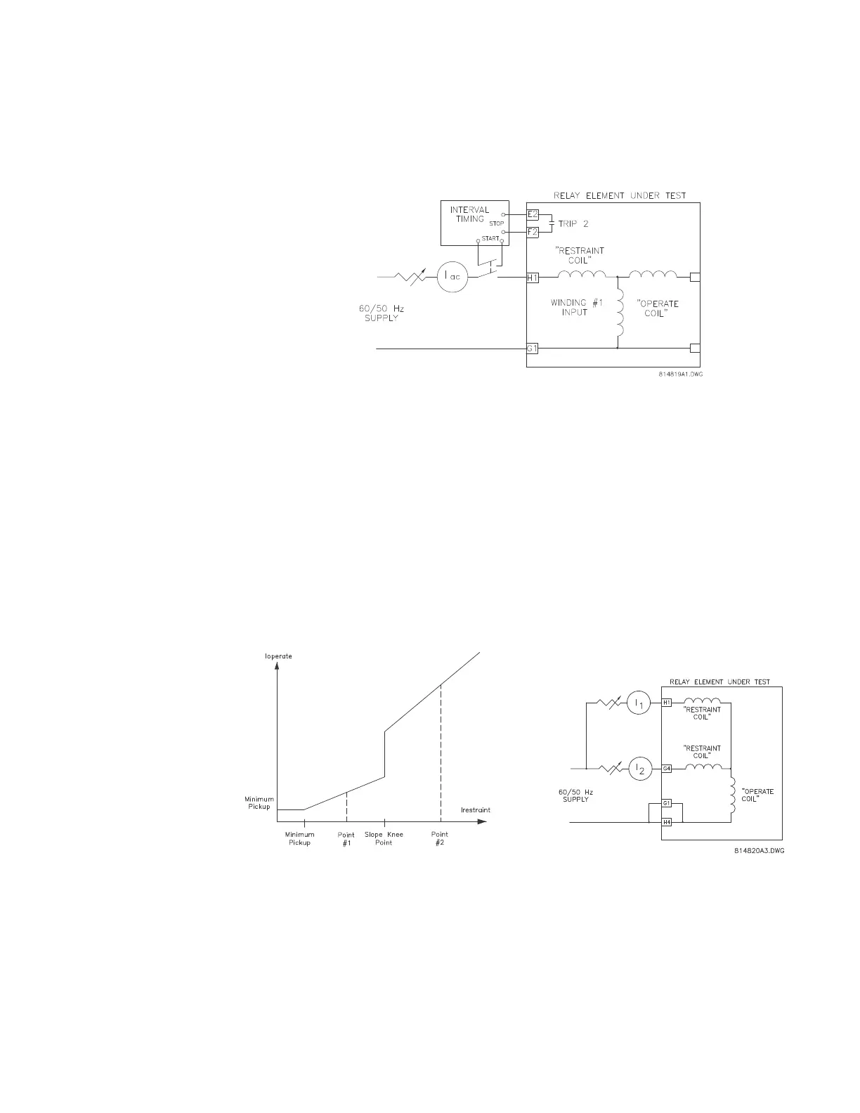
FIGURE 7–5: Timer test circuit
7.5.2.7 Slope Measurements
The auto configuration processes the currents to correct for phase shifts, CT mismatch,
and zero sequence component removal. As such, it more complex to measure the slope
from an external single phase injection. Therefore, the use of displayed actual values is
recommended.
The differential and restraint currents are displayed the A2 METERING
CURRENT
DIFFERENTIAL
PHASE A DIFFERENTIAL CURRENT and A2 METERING CURRENT
RESTRAINT
PHASE A RESTRAINT CURRENT actual values:
To measure the slope,
Connect current signals to the relay as shown in the figure below:
FIGURE 7–6: Current signal connections
If I
1
= 1.5 × CT and I
2
= 0, the element is operated as all the current appears as a differential
current.
The slope is calculated from the values of I
differential
and I
restraint
as follows:
%slope
I
differential
I
restraint
-------------------------
100%×=
 Loading...


