CHAPTER 7: COMMISSIONING PROTECTION SCHEMES
745 TRANSFORMER PROTECTION SYSTEM – INSTRUCTION MANUAL 7–21
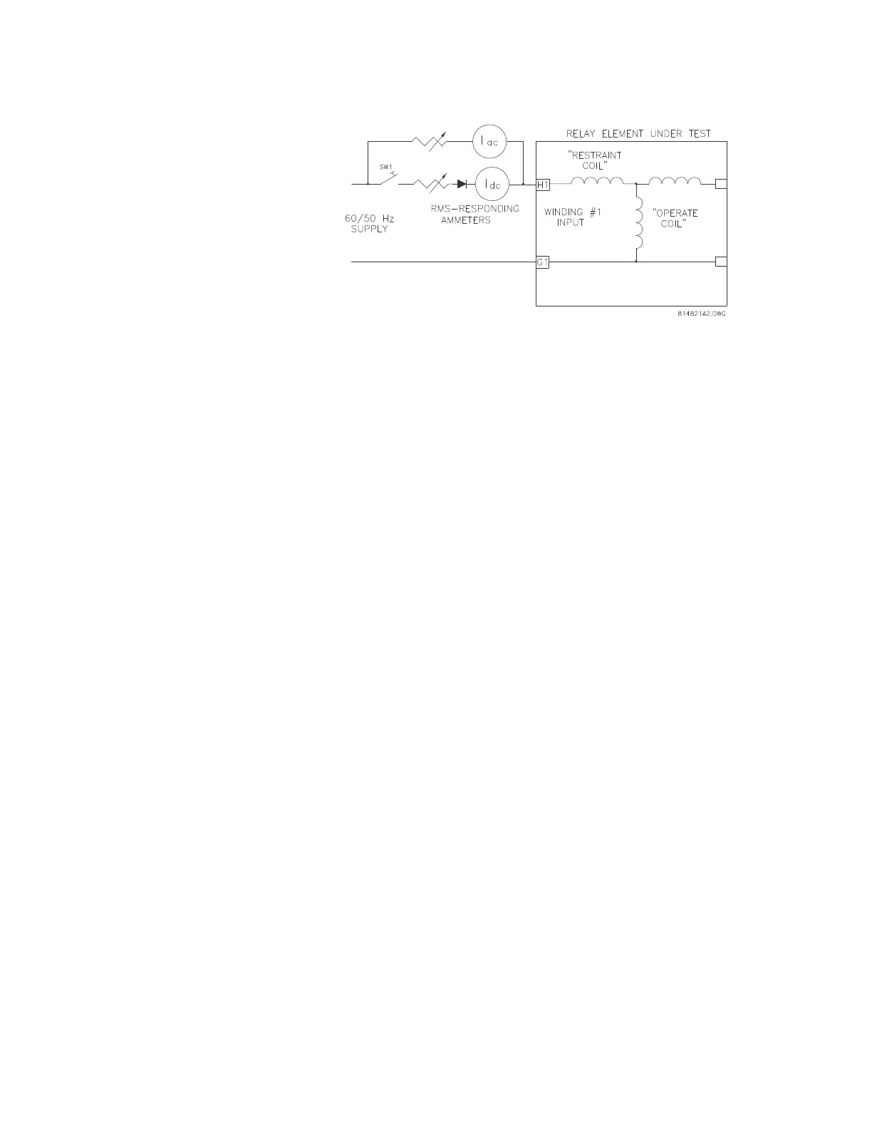
FIGURE 7–7: Second harmonic restraint testing
Close switch S1. Set the AC current, I
AC
to 2 × rated CT secondary. Set
I
DC
to obtain harmonic content above the 2nd harmonic restraint setting
under
S4 ELEMENTS DIFFERENTIAL HARMONIC INHIBIT
HARMONIC INHIBIT LEVEL.
Calculate the percent second harmonic content from the following
equations. If the current is measured with average-responding/reading
meters:
If the current is measured with RMS-responding/reading meters, then:
Open and reclose S1. The relay should not operate.
Decrease I
DC
until the element operates. Calculate the percent of second
harmonic at this point using the equations above. The calculated percent
harmonic value should equal the relay setting.
7.5.2.10 Fifth Harmonic Restraint
Verifying the operation of the 5th harmonic restraint requires test equipment capable of
generating a current signal containing a fundamental and 5th harmonic. Most modern
dedicated relay test instruments, such as Powertec's (or Manta) DFR, Doble, or MultiAmp
instruments are capable of generating appropriate signals. A power operational amplifier
with a suitably rated output, or a power audio amplifier, may also be used to generate the
appropriate signal.
Connect the test setup as below to supply the phase A element. Set the
fundamental current level to the CT rated secondary value. The
harmonic restraint differential element of phase A should be operated.
%2nd
100 0.424 I
DC
××
I
DC
0.9 I
AC
×+
-------------------------------------------
=
%2nd
100 0.424 I
DC
××
I
DC
1.414 I
AC
×+
-------------------------------------------
=