7–22 745 TRANSFORMER PROTECTION SYSTEM – INSTRUCTION MANUAL
PROTECTION SCHEMES CHAPTER 7: COMMISSIONING
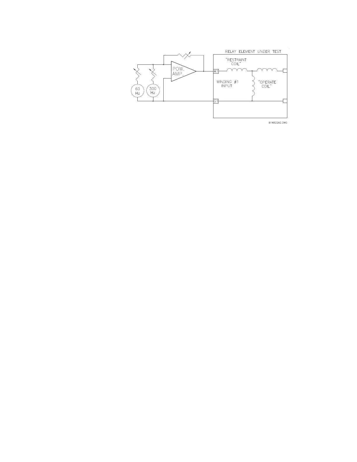
FIGURE 7–8: Fifth harmonic restraint testing
Increase the 5th harmonic component to a value well above the S4
ELEMENTS
DIFFERENTIAL 5th HARM INHIBIT 5th
HARMONIC INHIBIT LEVEL setting.
Remove the total current signal and reapply.
The relay should not operate.
Decrease the 5th harmonic component until the element operates.
Calculate the percentage 5th harmonic to restrain from the following
equation:
Compare this value to the relay setting.
7.5.2.11 Energization Detection Scheme
Refer to Differential Element on page 5–48 for a description of this feature. This feature is
activated by up to three inputs: breaker auxiliary switch, current below a threshold, or
absence of voltage. The procedure below tests the current-level enabling feature. A similar
approach can verify the other two enabling functions with the proper test equipment.
Enable the Energization Detection Scheme by setting
S4 ELEMENTS
DIFFERENTIAL ENERGIZATION INHIBIT ENERGIZATION INHIBIT
FUNCTION
to Enabled.
Make the following setpoint changes in the
S4 ELEMENTS
DIFFERENTIAL
ENERGIZATION INHIBIT setpoints menu:
ENERGIZATION INHIBIT PARMETERS: “2nd”
HARMONIC AVERAGING: “Disabled”
ENERGIZATION INHIBIT LEVEL: “15%”
ENERGIZATION INHIBIT DURATION: “5 s”
ENERGIZATION SENSING BY CURRENT: “Enabled”
ENERGIZATION INHIBIT/MINIMUM ENERGIZATION CURRENT: “0.10
× CT”
Preset current with harmonic content just above the
ENERGIZATION
INHIBIT LEVEL used during the ‘energization period’.
%5th
100 level of 5th harmonic×
level of fundamental
---------------------------------------------------------------------
=