Section 20 - Appendix C–Filter Board Options PWA 148921-01
133
20.13 Test Filter Option (Alternate Procedure)
This procedure should only be used when your Full Scale Range Option is 05, 06, 15, 16,
or 17 (see Section 8.2) and the full scale amplitude calculated in step 5b of the main
procedure (Section 20.12) is greater than 3.5V or too small to set up accurately on your
function generator.
Note: Both channels A and B must be calibrated before performing this test (see Section
15). Test equipment should be set up as shown in step two of Section 20.12. If barriers
are used, test with barriers in place.
1. Configure the main board as follows to change the Integrator Stage to a Gain
Stage:
Channel A: Install W6B,C
Remove W6A
Channel B: Install W3D,E
Remove W3F
2. Adjust the frequency of the function generator to the -3dB frequency of the filter.
For High Pass Filters, the -3dB frequency is the corner frequency chosen in
Section 20.7 or 20.8. For Low Pass Filters, the -3dB frequency is the corner
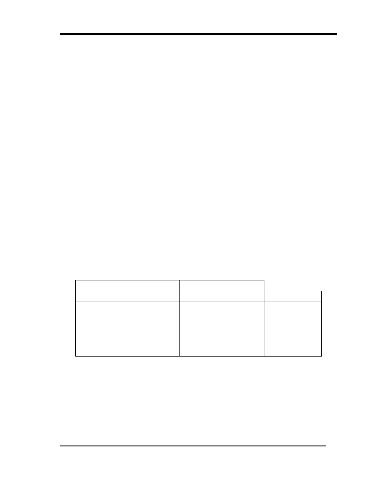
frequency chosen in Section 20.10. Set the amplitude of the function generator
for a full scale sine wave signal with a -7.5 Vdc offset:
3. Verify that the front panel bargraph for the channel being tested reads 65% to
75% of full scale range.
4. If you are testing a Band Pass Filter, repeat steps two and three at the second -
3dB frequency.
Full Scale Input Voltage Full Scale Option
Vpk Vrms
05 0-1 in/s
06 0-2 in/s
15 0-25 mm/s
16 0-50 mm/s
17 0-100 mm/s
0.500
1.00
0.492
0.984
1.969
0.354
0.707
0.348
0.696
1.392
 Loading...


