Section 18 - Appendix A–Main Board Options
53
18.7 Main Board Buffered Out and Filter Options
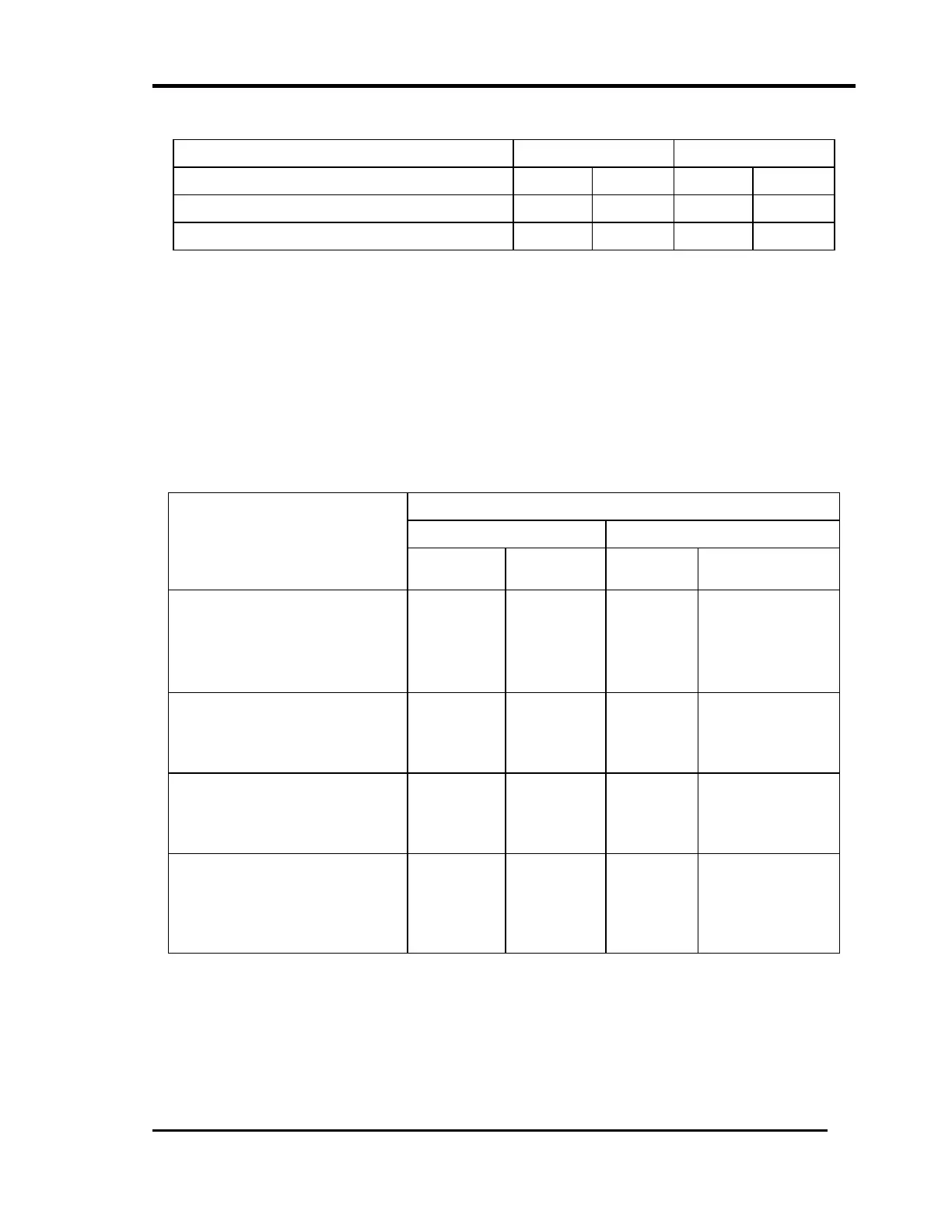
BUFFERED TRANSDUCER OUTPUT
CHANNEL A CHANNEL B
INSTALL REMOVE INSTALL REMOVE
* Buffered transducer output not filtered. W18C W18A W5C W5A
Buffered transducer output filtered W18A W18C W5A W5C
* Standard configuration.
When this option is selected, the buffered transducer output follows the
Integrator/Gain Stage. For a true unfiltered output, all filters should be located after
the Integrator/Gain Stage.
If any filters are located before the Integrator/Gain Stage, the buffered transducer
output will be filtered by those filters. Refer to Figure 1 in Section 19.3 (duplicated in
Section 20.3).
The table below shows the configuration of the Integrator/Gain stage. The
configuration of the Integrator/Gain stage is described in Sections 19.6 and 20.6.
Main Board
Channel A Channel B
INTEGRATOR/GAIN STAGE
LOCATION
INSTALL REMOVE INSTALL REMOVE
** Integrator/Gain Stage
with
NO Filtering
W18B
W6E
W6D
W6F
W5B
W3B
W3A
W3C
*** Filter after
Integrator/Gain Stage
W6E
W6D
W6F
W18B
W3B
W3A
W3C
W5B
Filter before
Integrator/Gain Stage
W6D
W6F
W18B
W6E
W3A
W3C
W5B
W3B
High Pass Filter before
Integrator/Gain Stage and
Low Pass Filter after the
Integrator/Gain Stage
W6D
W6F
W6E
W18B
W3A
W3C
W3B
W5B
** Denotes standard configuration
*** When filtering without integration, set the filter after the Integrator/Gain Stage.
 Loading...


