Section 19 - Appendix B–Filter Board Options PWA 79562-01 and PWA 105521-01
73
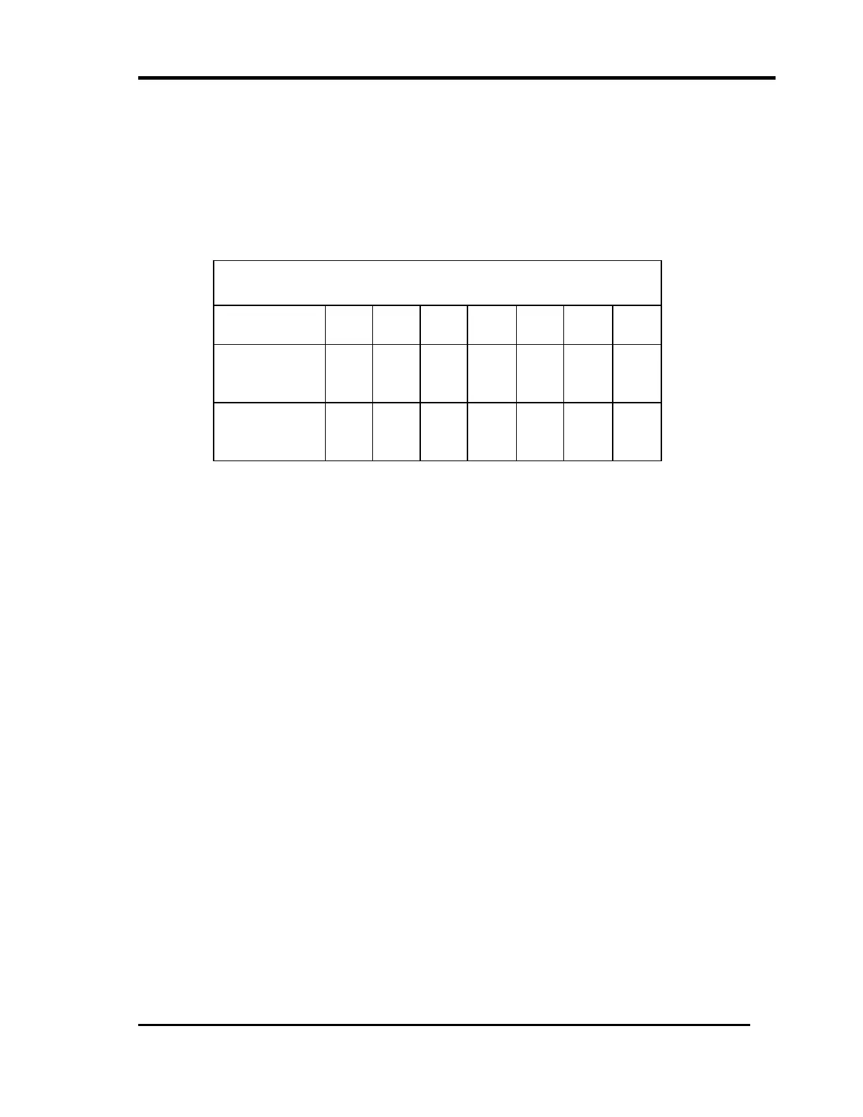
4. Set the jumpers for the input clock frequency (f
CLK
) according to this table.
R = REMOVE JUMPER, I = INSTALL JUMPER
5. Set the jumpers for the Divider ratio D according to the table on the following
page.
SWITCHED CAPACITOR FILTER INPUT CLOCK JUMPER
TABLE
CHANNEL A -
CHANNEL B -
W1
W7
W3
W8
W4
W9
W5
W10
W6
W2
W87
W89
W88
W90
3.58 MHZ
2 MHZ
1 MHZ
R
I
R
R
R
I
R
R
R
R
R
R
R
R
R
I
R
R
R
I
I
500 kHz
250 kHz
125 kHz
R
R
R
R
R
R
I
R
R
R
I
R
R
R
I
R
R
R
I
I
I
 Loading...


