GE Multilin C30 Controller System B-35
APPENDIX B B.4 MEMORY MAPPING
B
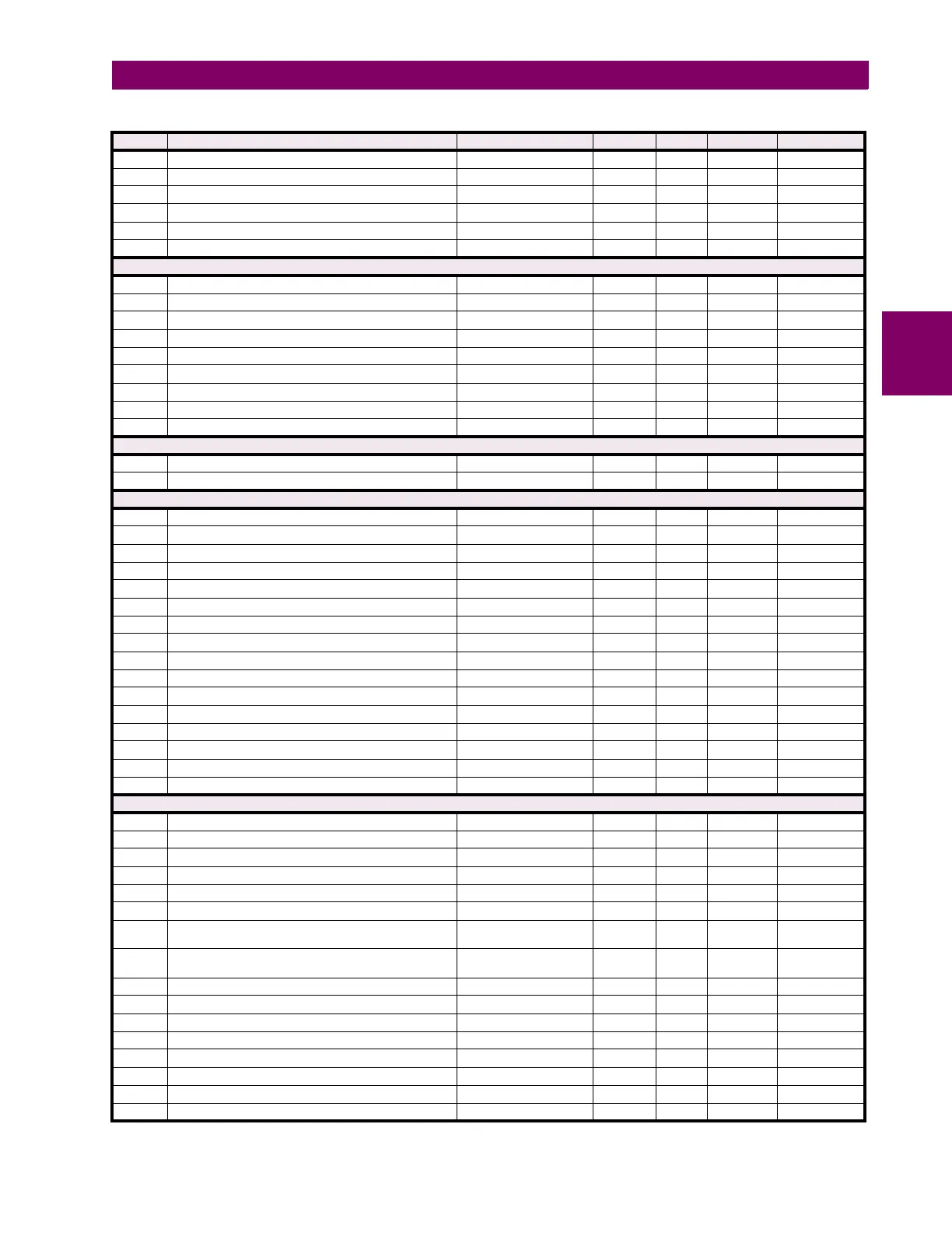
9995 Teleprotection Terminal 2 ID 0 to 255 --- 1 F001 0
9996 Reserved (10 items) 0 to 1 --- 1 F001 0
9A00 Teleprotection Input 1-n Default States (16 items) 0 to 3 --- 1 F086 0 (Off)
9A10 Teleprotection Input 2-n Default States (16 items) 0 to 3 --- 1 F086 0 (Off)
9A20 Teleprotection Output 1-n Operand (16 items) 0 to 4294967295 --- 1 F300 0
9A40 Teleprotection Output 2-n Operand (16 items) 0 to 4294967295 --- 1 F300 0
Teleprotection Channel Tests (Read Only)
9AA0 Teleprotection Channel 1 Status 0 to 2 --- 1 F134 1 (OK)
9AA1 Teleprotection Channel 1 Number of Lost Packets 0 to 65535 --- 1 F001 0
9AA2 Teleprotection Channel 2 Status 0 to 2 --- 1 F134 2 (n/a)
9AA3 Teleprotection Channel 2 Number of Lost Packets 0 to 65535 --- 1 F001 0
9AA4 Teleprotection Network Status 0 to 2 --- 1 F134 2 (n/a)
9AAF Teleprotection Channel 1 Input States 0 to 1 --- 1 F500 0
9AB0 Teleprotection Channel 2 Input States 0 to 1 --- 1 F500 0
9AC0 Teleprotection Input 1 States, 1 per register (16 items) 0 to 1 --- 1 F108 0 (Off)
9AD0 Teleprotection Input 2 States, 1 per register (16 items) 0 to 1 --- 1 F108 0 (Off)
Selector Switch Actual Values (Read Only)
A210 Selector Switch 1 Position 1 to 7 --- 1 F001 0
A211 Selector Switch 2 Position 1 to 7 --- 1 F001 1
Selector Switch Settings (Read/Write) (2 modules)
A280 Selector 1 Function 0 to 1 --- 1 F102 0 (Disabled)
A281 Selector 1 Range 1 to 7 --- 1 F001 7
A282 Selector 1 Timeout 3 to 60 s 0.1 F001 50
A283 Selector 1 Step Up 0 to 4294967295 --- 1 F300 0
A285 Selector 1 Step Mode 0 to 1 --- 1 F083 0 (Time-out)
A286 Selector 1 Acknowledge 0 to 4294967295 --- 1 F300 0
A288 Selector 1 Bit0 0 to 4294967295 --- 1 F300 0
A28A Selector 1 Bit1 0 to 4294967295 --- 1 F300 0
A28C Selector 1 Bit2 0 to 4294967295 --- 1 F300 0
A28E Selector 1 Bit Mode 0 to 1 --- 1 F083 0 (Time-out)
A28F Selector 1 Bit Acknowledge 0 to 4294967295 --- 1 F300 0
A291 Selector 1 Power Up Mode 0 to 2 --- 1 F084 0 (Restore)
A292 Selector 1 Target 0 to 2 --- 1 F109 0 (Self-reset)
A293 Selector 1 Events 0 to 1 --- 1 F102 0 (Disabled)
A294 Reserved (10 items) --- --- 1 F001 0
A29E ...Repeated for Selector 2
Digital Counter (Read/Write Setting) (8 modules)
A300 Digital Counter 1 Function 0 to 1 --- 1 F102 0 (Disabled)
A301 Digital Counter 1 Name --- --- --- F205 “Counter 1"
A307 Digital Counter 1 Units --- --- --- F206 (none)
A30A Digital Counter 1 Block 0 to 4294967295 --- 1 F300 0
A30C Digital Counter 1 Up 0 to 4294967295 --- 1 F300 0
A30E Digital Counter 1 Down 0 to 4294967295 --- 1 F300 0
A311 Digital Counter 1 Preset –2147483647 to
2147483647
--- 1 F004 0
A313 Digital Counter 1 Compare –2147483647 to
2147483647
--- 1 F004 0
A315 Digital Counter 1 Reset 0 to 4294967295 --- 1 F300 0
A317 Digital Counter 1 Freeze/Reset 0 to 4294967295 --- 1 F300 0
A319 Digital Counter 1 Freeze/Count 0 to 4294967295 --- 1 F300 0
A31B Digital Counter 1 Set To Preset 0 to 4294967295 --- 1 F300 0
A31D Reserved (11 items) --- --- --- F001 0
A328 ...Repeated for Digital Counter 2
A350 ...Repeated for Digital Counter 3
A378 ...Repeated for Digital Counter 4
Table B–10: MODBUS MEMORY MAP (Sheet 27 of 48)
ADDR REGISTER NAME RANGE UNITS STEP FORMAT DEFAULT