Chapter 2: Installation
16 Concord 4 Installation Manual
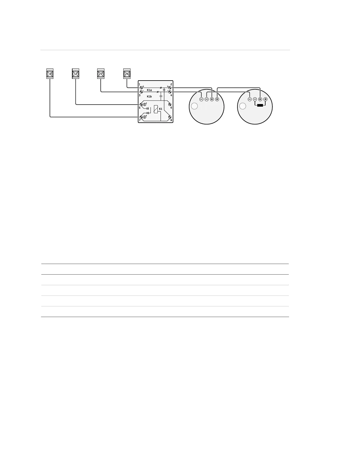
Figure 8: Polarity reversal module
OUT 2
+12V GND
ZONE 8
2W-SMK
Polarity reversal
module (part # 405-03)
521NCSXT
521NCSXT
Four-wire smoke detectors
Terminal 24 provides power to four-wire smoke detectors that latch and remain in
the alarm state until power turns off, then restores to the detector. The panel
provides this power interruption from terminal 24 (2W SMK ZONE 8) only when the
two-wire smoke option is on.
Note: The two-wire smoke feature must be on for smoke detectors to reset after
canceling a fire alarm.
Table 7 below describes the minimum available panel power. Use only four-wire
smoke detectors that operate at these power limits. Connect up to five smoke
detectors as shown in Figure 7 on page 15.
Table 7: Minimum available panel power
Minimum voltage Maximum current available
8.3 VDC Up to 30 mA total (combined alarm) current
8.1 VDC Up to 40 mA total (combined alarm) current
7.6 VDC Up to 60 mA total (combined alarm) current
7.1 VDC Up to 80 mA total (combined alarm) current

 Loading...