Chapter 3: Programming
72 Concord 4 Installation Manual
Partition assign This menu lets you assign bus devices to work in the desired partition.
Note: SuperBus 2000 8Z input modules, SuperBus 2000 4-relay output
modules, and SuperBus 2000 RF receivers are not assigned to partitions.
To assign bus devices to partitions:
1. With the display showing the desired bus device, press #.
2. Press A or B until the display shows DEVICE PTN and then press #. The
display shows PARTITION ASSIGN n.
3. Press 1 to 6 to select the desired partition. The display flashes the entered
selection. Press # and the display shows the new setting.
Output programming Use these settings to program the output points of any installed SuperBus
2000 hardwire output module. The installer programs a HOM output point
into the Concord security panel by entering three kinds of information.
• Partition: The system partition (1 to 6).
•Trigger: The event that activates the output point. Trigger events can be
partition alarms, trouble conditions, open sensors, etc.
• Response: How the output responds to a trigger event.
Only the onboard and SnapCard outputs can be configured for user control.
To program each of the HOM output point configurations into the security
panel:
1. With the display showing the desired bus device, press #.
2. Press A or B until the display shows OUTPUTS.
3. Press #. The display shows OUTPUT 1.
4. Press A or B to select an output, then press #. The display shows
PARTITION ASSIGN 1.
5. Press 1 to 6 to select the desired partition assignment for this relay. The
display flashes the entered setting. Press # and the display shows the new
setting.
6. Press A or B. The display shows CONFIGURATION tttrr (current
setting). The point configuration number is tttrr, where ttt is the trigger
number and rr is the response number.
7. Enter the desired five-digit configuration number for this relay. The
display flashes the entered setting. Press # and the display shows the new
setting.
8. Press # and repeat the process until all outputs are programmed.
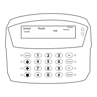
Status beeps
Default: On
This setting determines whether the selected touchpad sounds status
beeps. Each touchpad can be set individually. This feature is usually turned
off for a touchpad that is located in or near bedrooms, to avoid disturbing
sleeping persons.
Key beeps
Default: On
This setting determines whether or not selected touchpads beep when their
buttons are pressed. This feature is usually turned off for a touchpad that is
located in or near bedrooms, to avoid disturbing sleeping persons.
 Loading...
