DigitalFlow™ XMT868i Startup Guide 17
Chapter 1. Installation
1.7.5h Wiring the MODBUS Option Card
The MODBUS option card uses the RS485 standard for MODBUS communication. The MODBUS card must be
installed in Slot 2. The RS485 standard allows up to 32 nodes (drivers and receivers) on one multi-drop network, at
distances up to 4,000 ft (1,200 m). GE recommends using 24-gauge (24 AWG) twisted-pair wire with a characteristic
impedance of 120 ohms and 120-ohm termination at each end of the communications line.
Note: The MODBUS option card provides its own RS485 connections. Thus, the meter can have its serial port
configured as RS232 and still provide RS485 MODBUS signals.
IMPORTANT: Because the MODBUS option card uses pins 1 and 2 on terminal block J2, only those option cards that
do not use these pins may be installed in Slot 1, while a MODBUS card is installed in Slot 2.
Specifically, only the option cards designated as “OI” and “OR” in Figure 11 on page 24 are
compatible with the MODBUS option card.
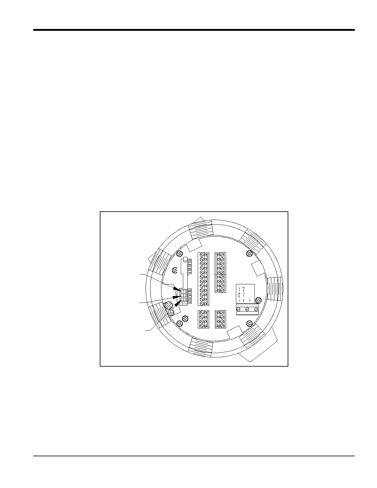
To link the XMT868i to the control system (refer to Figure 7 below):
1. Connect the MODBUS– wire to pin
#2, the inverting or negative connection.
2. Connect the MODBUS+ wire to pin
#1, the non-inverting or positive connection.
3. Pin #3 has no connection.
Figure 7: The RS485 MODBUS Terminal Block Connector