5-12 F650 Digital Bay Controller GEK-106310AB
5.2 PRODUCT SETUP 5 SETTINGS
5
5.2.4.3 OSCILLOGRAPHY STATES
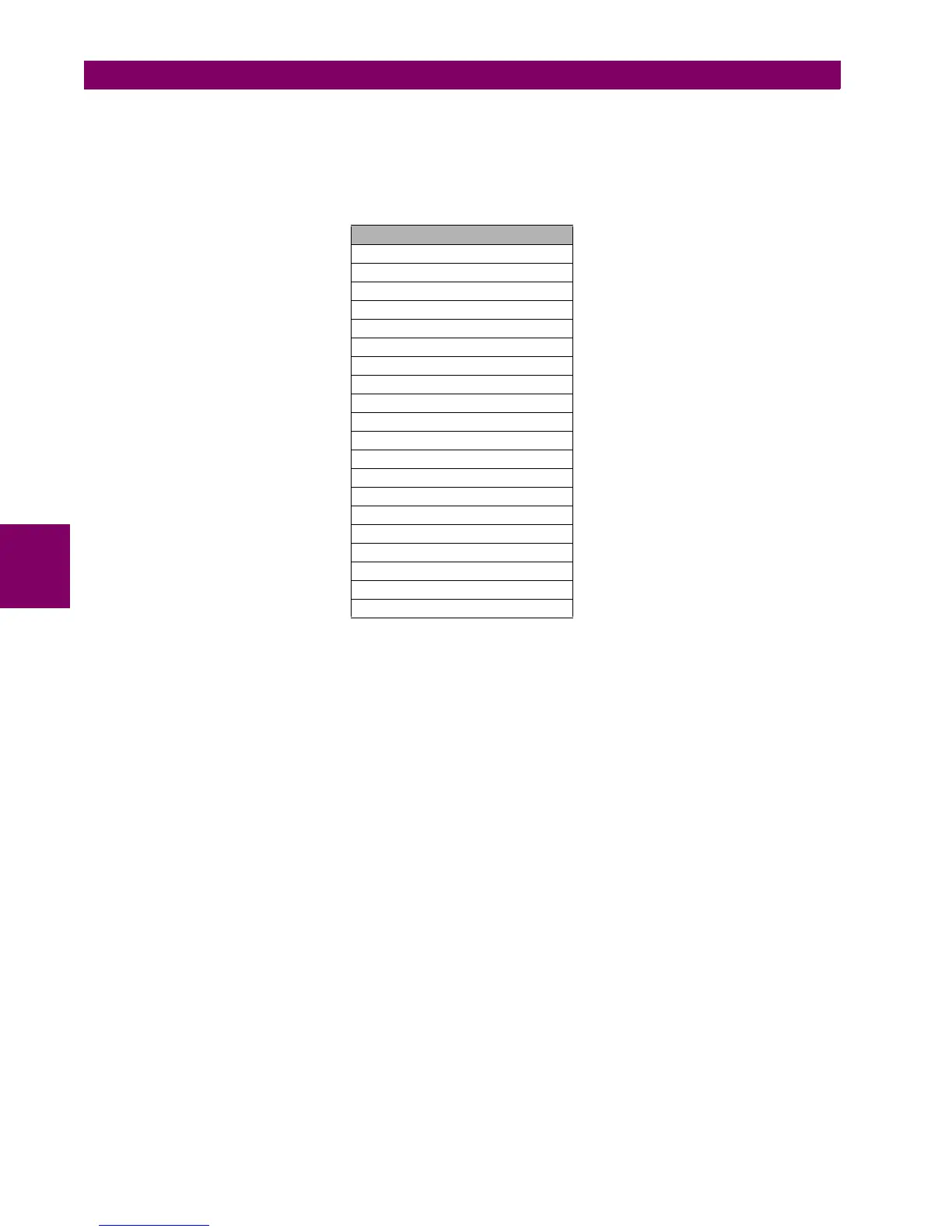
States associated to the oscillography module (“Actual >Status>Records Status>Oscillography”), are shown in Table 5–
12:
Table 5–12: OSCILLOGRAPHY STATES
OSC DIGITAL CHANNEL XX: These states are configured at “Setpoint>Relay configuration>Oscillography”.
Each of these states can be associated to a protection state or to a virtual output. Each
oscillography record will reflect the changes experienced by this state during the
record.
OSCILLO TRIGGER: The activation of this state will produce the oscillography record capture. Each record
uses a percentage of its capacity to store prefault information. This percentage is
selected in the Trigger Position setting, and the rest of the record’s capacity will store
post-fault information.
NUMBER OF TRIGGERS: This is the number of the most recent oscillography record stored in the relay. The
record is stored in COMTRADE format. The range is 0 to 999.
CYCLES PER RECORD: This state displays the number of cycles that will be stored in each oscillography
record. Although the number of cycles can be a decimal number, the record will
represent only the integer part.
AVAILABLE RECORDS: This shows the number of records stored in the relay, which can be retrieved by serial
communication (ModBus RTU) or Ethernet (ftp, tftp). The range is 0 to 20.
OSCILLOGRAPHY STATES
OSC DIG CHANNEL 1
OSC DIG CHANNEL 2
OSC DIG CHANNEL 3
OSC DIG CHANNEL 4
OSC DIG CHANNEL 5
OSC DIG CHANNEL 6
OSC DIG CHANNEL 7
OSC DIG CHANNEL 8
OSC DIG CHANNEL 9
OSC DIG CHANNEL 10
OSC DIG CHANNEL 11
OSC DIG CHANNEL 12
OSC DIG CHANNEL 13
OSC DIG CHANNEL 14
OSC DIG CHANNEL 15
OSC DIG CHANNEL 16
OSCILLO TRIGGER
NUMBER OF TRIGGERS
CYCLES PER RECORD
AVAILABLE RECORDS