5-66 F650 Digital Bay Controller GEK-106310AB
5.4 PROTECTION ELEMENTS 5 SETTINGS
5
5.4.6.2 SENSITIVE GROUND INSTANTANEOUS OVERCURRENT ELEMENT (50SG)
50SG is a sensitive ground instantaneous overcurrent protection element, with a setting range from 0.005 A to 16.00 A,
which can also be time delayed, with a delay selectable between 0 and 900 seconds. The ground current input quantity is
measured from the sensitive ground input, and it may be programmed as fundamental phasor magnitude or RMS
magnitude as required by the application. The element incorporates a reset time selectable between 0 and 900 seconds,
and a block input that resets the pickup and trip signals to 0. The element outputs are the general pickup and trip signals of
the element.
Table 5–59: 50SG ELEMENT SETTINGS
The snapshot event setting enables or disables the snapshot event generation for this element.
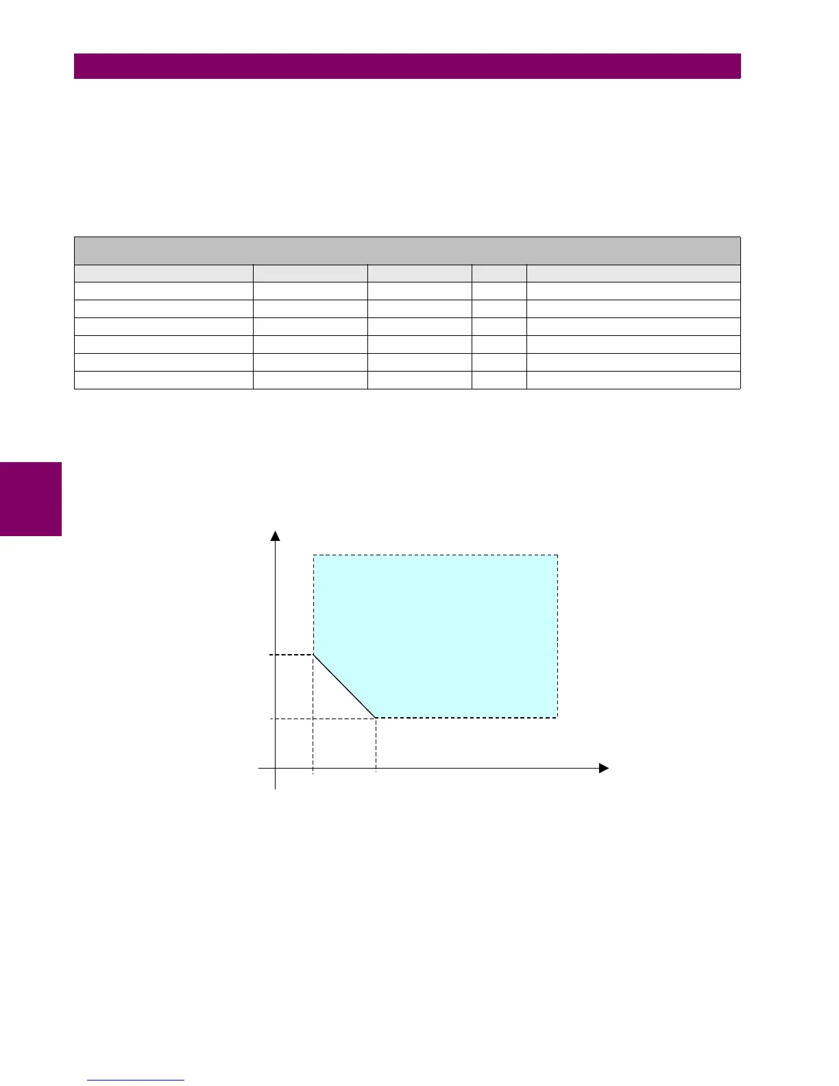
5.4.6.3 INSTANTANEOUS OVERCURRENT ELEMENT FOR UNGROUNDED SYSTEMS (50IG)
The operation of this element is similar to sensitive ground overcurrent elements; the difference is that in this case, 3I0
current is capacitive, and uses very reduced magnitudes (0.5-10 A primary values).
The operation characteristic is shown on figure Figure 5–14:, where Vh, Vl, Ih and Il are element settings.
Figure 5–14: OPERATION CHARACTERISTIC FOR ELEMENT 50IG
SETPOINT > PROTECTION ELEMENTS > SENSITIVE GROUND CURRENT > SENSITIVE GROUND IOC
SENSITIVE GROUND IOC 1> SENSITIVE GROUND IOC 2 > SENSITIVE GROUND IOC 3
SETTING DESCRIPTION NAME DEFAULT VALUE STEP RANGE
Function permission Function DISABLED N/A [DISABLED – ENABLED]
Input type Input PHASOR(DFT) N/A [PHASOR – RMS]
Pickup level Pickup Level 0.100 0.001 A [0.005 : 16.000]
Trip time Trip Delay 0.00 0.01 s [0.00 : 900.00]
Reset time Reset Delay 0.00 0.01 s [0.00 : 900.00]
Snapshot event generation Snapshot Events ENABLED N/A [DISABLED – ENABLED]
eration Area
I
h
I
l
V
l
V
h
V
n
=3V
0
I
n
=3I
0