GEK-106310AB F650 Digital Bay Controller 5-73
5 SETTINGS 5.4 PROTECTION ELEMENTS
5
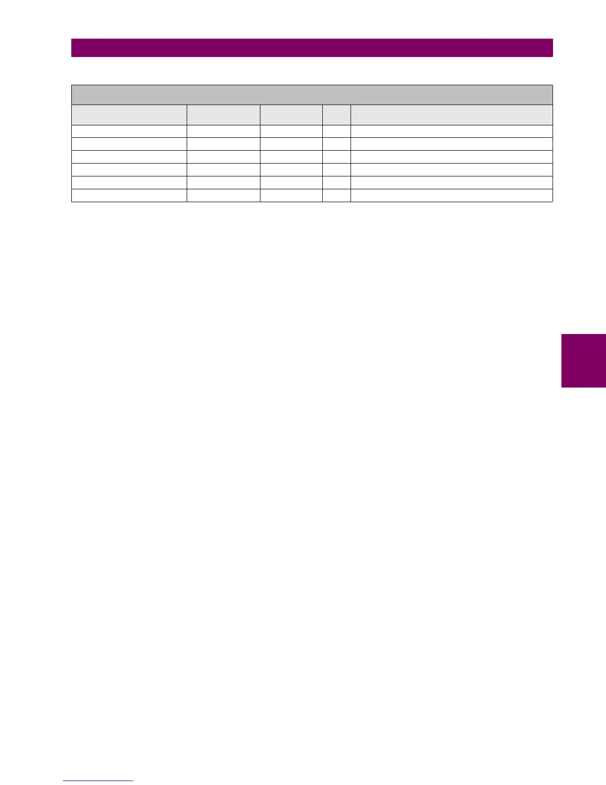
Table 5–65: 59P ELEMENT SETTINGS
Phase overvoltage element settings are:
Function Permission (Function): This setting indicates whether the phase overvoltage element is enabled or disabled.
Pickup Level: This is the voltage threshold over which the overvoltage element will operate.
Trip time (Trip Delay): setting of the Protection element operation time.
Reset time (Reset Delay): Reset time of the Protection element.
Operation logic (Logic): This setting allows the element operation logic selection:
ANY PHASE The element will operate under an overvoltage condition in any of the
three phases.
TWO PHASES The element will operate under an overvoltage condition in at least
two phases.
ALL PHASES The element will operate under an overvoltage condition in the three
phases.
Snapshot Events: The snapshot event setting enables or disables the snapshot event generation for this
element.
5.4.8.3 NEUTRAL OVERVOLTAGE ELEMENT (HIGH LEVEL AND LOW LEVEL) (59NH/59NL)
The Neutral Overvoltage element can be used to detect an asymmetrical system voltage condition due to a ground fault or
to the loss of one or two phases of the source.
The element responds to the system neutral voltage (3V0), calculated from the phase voltages or measured by the 4th
voltage transformer.
VT errors and normal voltage unbalance must be considered when setting this element.
The element time delay is selectable between 0 and 900 seconds and incorporates a reset with a selectable delay between
0 and 900 seconds.
Notice that the neutral overvoltage element will not be available if a DELTA Connection is set in the Phase VT Connection
setting in General settings, and the fourth voltage transformer input is set to the busbar voltage for the synchronism
element (Vx in Auxiliary Voltage setting). This is because with this combination of settings it is not possible to calculate the
zero sequence component from the phase-to-phase voltage magnitudes.
SETPOINT > PROTECTION ELEMENTS > VOLTAGE ELEMENTS > PHASE OV >
PHASE OV 1> PHASE OV 2 > PHASE OV 3
SETTING DESCRIPTION NAME DEFAULT
VALUE
STEP RANGE
Function permission Function DISABLED N/A [DISABLED – ENABLED]
Pickup Level Pickup Level 10 1 V [3 : 300]
Trip time Trip Delay 10.00 0.01 s [0.00 : 900.00]
Reset time Reset Delay 0.00 0.01 s [0.00 : 900.00]
Operation logic Logic ANY PHASE N/A [ANY PHASE – TWO PHASES – ALL PHASES]
Snapshot Event generation Snapshot Events ENABLED N/A [DISABLED – ENABLED]