GEK-106310AB F650 Digital Bay Controller 5-83
5 SETTINGS 5.4 PROTECTION ELEMENTS
5
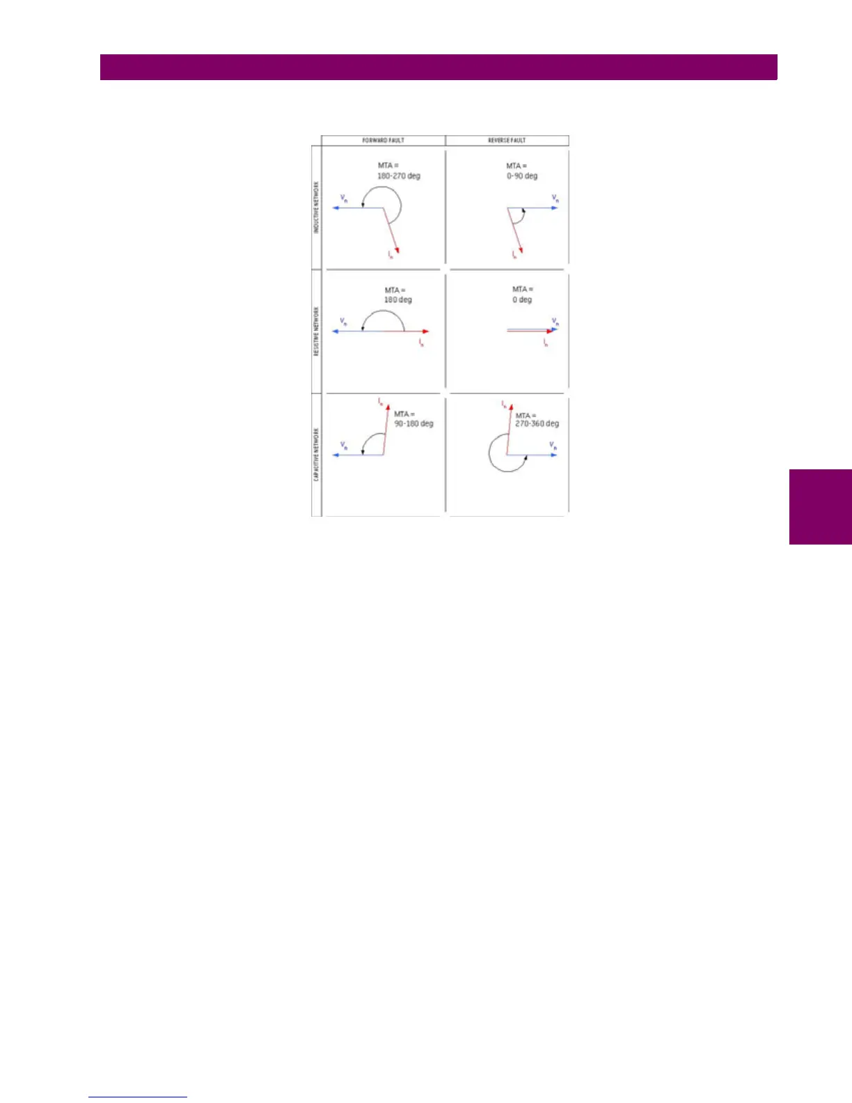
Figure 5–20: ANGLES
Operating power
V
n
– neutral voltage (3 times V_0): either calculated (VX as auxiliary voltage setting) or supplied from the Auxiliary
voltage channel (VN as auxiliary voltage setting)
I
n
– neutral current (3 times I_0): either calculated (IN as current selection setting) or supplied from the ground current
channel (IG as current selection setting)
The following figure shows the logic scheme diagram for high range and low range wattmetric ground fault elements
(32NH, 32NL).