7-84 F650 Digital Bay Controller GEK-106310AB
7.3 IEC 61850 CONFIGURATOR 7 IEC 61850 PROTOCOL
7
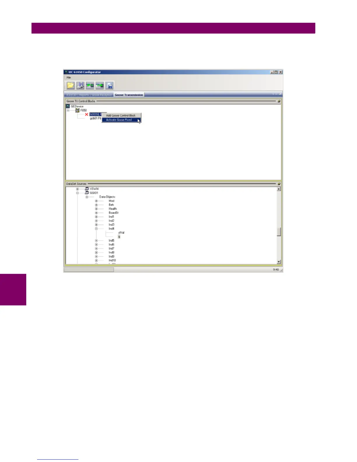
In order to enable/disable transmission of Fixed GOOSE the user should select with the mouse "GOOSE Fixed" control
block, right click on it and choose "Activate GOOSE Fixed" or "DeActivate GOOSE Fixed". When Fixed GOOSE has been
enabled the DataSet panel will remain empty as Fixed GOOSE always has the same Data Set (DNA and UserSt bits) which
cannot be modified.
Figure 7–27: FIXED GOOSE ACTIVATION/DEACTIVATION
For transmission GOOSE the user can create Data Sets with drag-and-drop selecting the desired data attributes in the data
model tree and dragging them to the DataSet panel. Data Sets can be directly formed by attributes of all Logical Nodes. For
example they can contains status of protection functions as:
• PTOC1.ST.Op.phsA- "Time Overcurrent Function 1 Operate Phase A"
• PTUF2.ST.Str.general- "Underfrequency Function 2 Trip General"
• XCBR1.ST.Pos.stVal- "Circuit Breaker Position"
•etc.
There is also a dedicated logical node in F650 which can be used for mapping of internal signals to be transmitted via
GOOSE. This logical node is rouGGIO1. It contains 32 digital indications with associated quality flags and timestamps.
rouGGIO1 permits flexible mapping of any of relay's digital signals to outgoing GOOSE messages. This can be useful when
transmission via GOOSE of internal signals that are not mapped to any IEC 61850 logical node in the F650 is required. An
example of such signals are "Virtual Outputs" which are internal variables of F650 derived from PLC logic equations.