A-2 F650 Digital Bay Controller GEK-106310AB
A.1 LOGIC OPERANDS APPENDIX A
A
Other internal states
USER MAP STATUS User map status: (0) Not configured ; (1) Configured
FACTORY
CALIBRATION
Calibration status (0) Relay calibrated; (1) Not calibrated
FLEXCURVE A STATUS User curve A: (0) Not configured (1) Configured
FLEXCURVE B STATUS User curve B: (0) Not configured (1) Configured
FLEXCURVE C STATUS User curve C: (0) Not configured (1) Configured
FLEXCURVE D STATUS User curve D: (0) Not configured (1) Configured
Green Zone Memory internal status
Yellow Zone Memory internal status
Orange Zone Memory internal status
Red Zone Memory internal status
UpTime System Time
Autocheck Internal States (Not available)
TIMER STATUS Real time clock autocheck (not available)
GRAPHIC STATUS Graphic display status (not available)
ALARM TEXT ARRAY Text display status (not available)
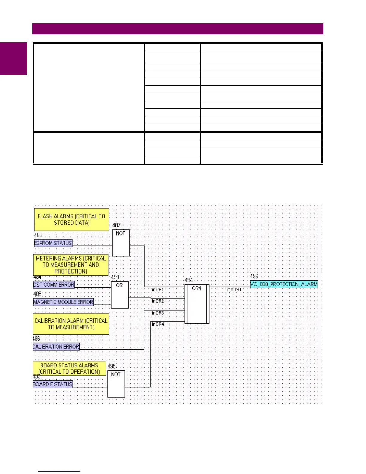
Note: It is advisable to use the critical alarms to raise an event or to light a warning led for maintenance purposes. See the
example below, the Board X Status depends on the relay model.
Figure A–1: PROTECTION ALARM SIGNAL