9
A Non-Combustible material with Fire Resistant Rating of
1 hour or greater
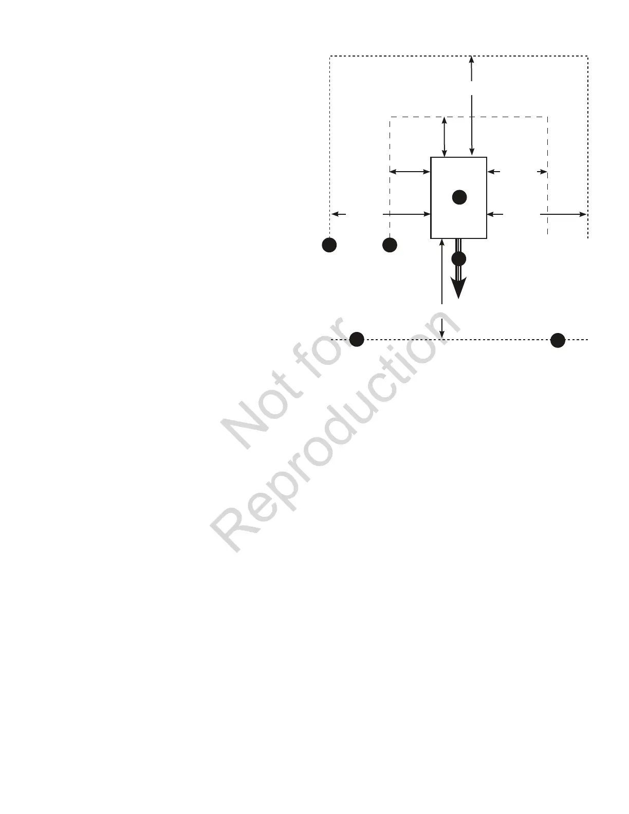
B Home Standby Generator
C Engine Exhaust
D Combustible Material or Structure with a Fire
Resistance Rating of less than 1 hour.
E Any structure or material. DO NOT connect (A) and/or
(D) to (E).
Install generator outdoors in an area which will not
accumulate deadly exhaust gas. DO NOT install generator
where exhaust gas could accumulate and enter inside or be
drawn into a potentially occupied building. Ensure exhaust
gas is kept away from windows, doors, ventilation intakes
or other openings that can allow exhaust gas to collect in a
confined area. Prevailing winds and air currents should be
taken into consideration when positioning generator.
General Location Guidelines
• InstalltheunitoutdoorsONLY.
• Placetheunitinapreparedlocationthatisflatand
has provisions for water drainage.
• Installtheunitinalocationwheresumppump
discharge, rain gutter down spouts, roof run-off,
landscape irrigation, or water sprinklers will not flood
the unit or spray the enclosure and enter any air inlet
or outlet openings.
• Installtheunitwhereitwillnotaffectorobstruct
any services (including covered, concealed and
underground), such as telephone, electric, fuel,
irrigation, air conditioning, and so forth.
• Installtheunitwhereairinletandoutletopenings
will not become obstructed by leaves, grass, snow,
etc. If prevailing winds will cause blowing or drifting,
you may need to construct a windbreak to protect
the unit.
• Installthegeneratorascloseaspossibletothe
transfer switch and fuel supply to reduce the length of
wiring, conduit, and piping.
Laws or local codes may regulate the distance to the
fuel supply.
The minimum clearances from aerial view of generator (B) to
combustible (D), and non-combustible (A) materials is shown
at right:
• Thesedistancesareprovidedtogivegenerator
location guidance relative ONLY to combustibles,
generator cooling, and maintenance.
• Theminimumdistancesinthefigureareasshown.
All four sides of the generator cannot be enclosed
or restricted, even if the minimum distances are
maintained. DO NOT connect (A) and/or (D) to (E)
• Aroofcannotbeused.
• Exhaust(C) must not be allowed to accumulate.
C
D
A
B
E
E
5’ (1.5 m)
3’ (1 m)
2’ (.62 m)
5’ (1.5 m)
5’ (1.5 m)
5’ (1.5 m)
 Loading...


