33
GE Title or job number
11/26/2013
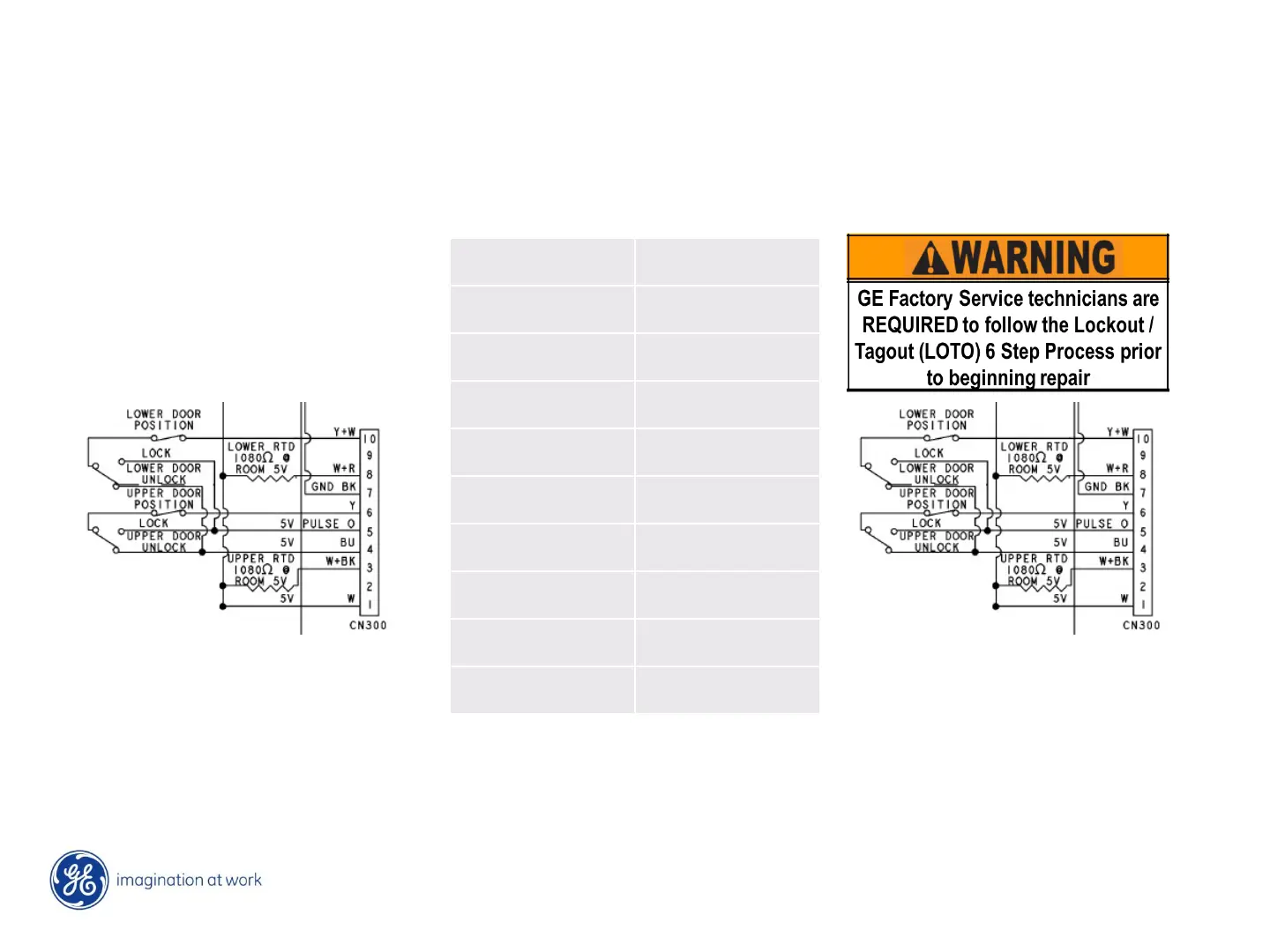
Oven sensor ERC (T012) F20 thru F35
As the oven sensor temperature increases its resistance also increases, voltage applied to the sensor circuit
varies accordingly. If the threshold setting in logic are exceeded then the board will set a F code. F codes
related to this include- F20, 21, 22, 23 – F30, 31, 32, 33, 34, 35.
Upper oven - wires 1 to 3 Lower oven wires - 1 to 8
Check resistance of oven sensor circuit on ERC (T012) at CN300 pin 1 to 3 W to W/BK for upper oven (F20, 21,
30, 31) and pin 1 to 8 W to W/R for lower oven (F22, 23, 32, 33)
°f =approx.
Ω
°f =approx.
Ω
°f =approx.
Ω
°f =approx.
Ω
°f =approx.
Ω
°f =approx.
Ω
°f =approx.
Ω
°f =approx.
Ω
°f =approx.
Ω
°f =approx.
Ω
°f =approx.
Ω
°f =approx.
Ω
°f =approx.
Ω
°f =approx.
Ω
°f =approx.
Ω
°f =approx.
Ω
°f =approx.
Ω
°f =approx.
Ω
 Loading...