Modifications reserved Page 27/103
OPM_LPS_33E_60K_M12_2GB_V010.doc Operating Manual LP 33 Series 60-80-100-120 kVA / S2
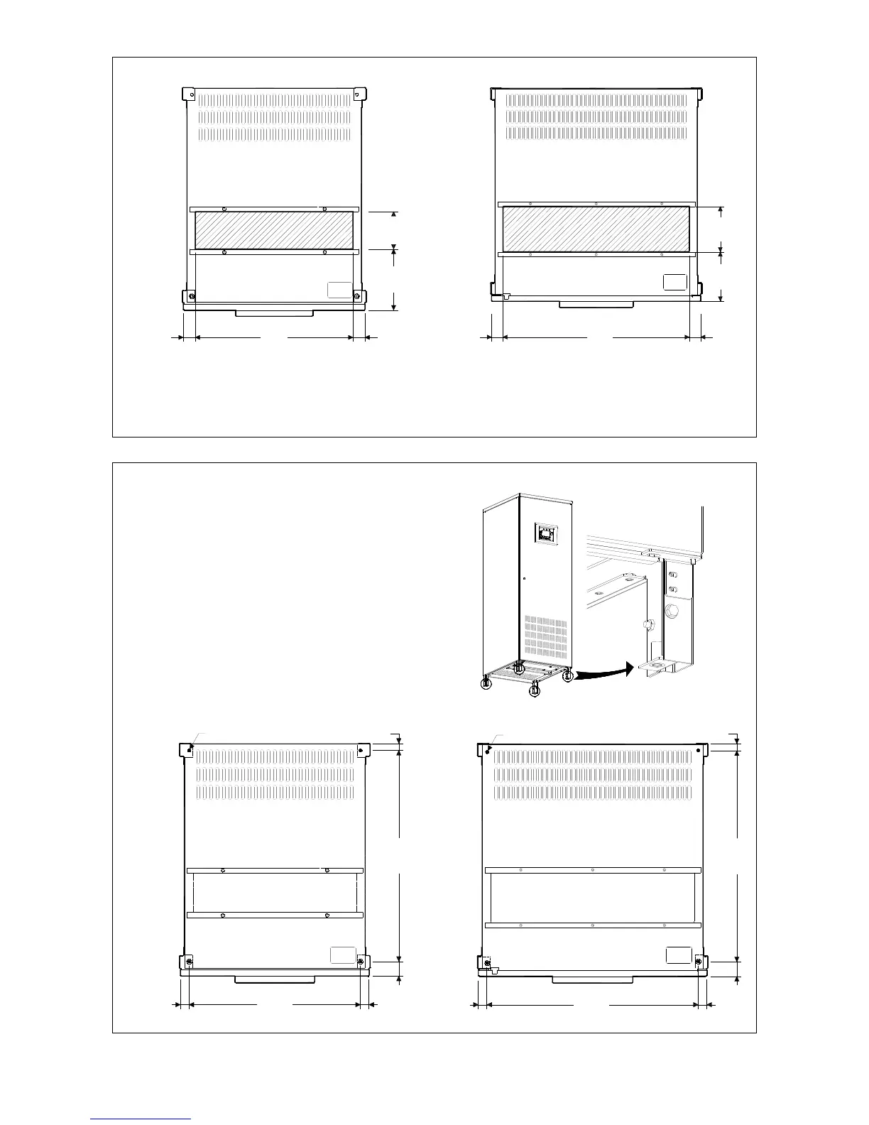
Opening for input and output cable connections LP 33 Series
LPS33_040-080_S2_UPS view bottom_01
195mm
512mm 44mm44mm
126mm
Fig. 5.4-2 LP 33 Series 60 - 80 kVA – Opening on the bottom cabinet
LPS33_100-120_S2_UPS view bottom_01
167mm
632mm 44mm44mm
154mm
Fig. 5.4-3 LP 33 Series 100 - 120 kVA - Opening on the bottom cabinet
LP 33 Series opening is provided on the bottom of the UPS for the connection of input and output
cables.
Pay attention to the position of this opening, when choosing the placement of the UPS.
Fixing of the UPS cabinet LP 33 Series on the floor
The UPS cabinet is free standing and normally
does not require to be bolted to the floor.
The UPS cabinet can be fixed however to the
floor by bolting it with the supporting blocks to
the floor.
LPS33_060-120_S2_UPS fixing_01
Fig. 5.4-4 Fixing of the UPS cabinet on the floor
LPS33_040-080_S2_UPS fixing_01
654mm
536mm 32mm
26mmØ 10mm
45mm
32mm
Fig. 5.4-5 LP 33 Series 60 - 80 kVA – UPS cabinet floor fixing points
654mm
26mm
45mm
LPS33_100-120_S2_UPS fixing_01
656mm 32mm
Ø 10mm
32mm
Fig. 5.4-6 LP 33 Series 100 - 120 kVA - UPS cabinet floor fixing points

 Loading...


