Modifications reserved Page 97/103
OPM_LPS_33E_60K_M12_2GB_V010.doc Operating Manual LP 33 Series 60-80-100-120 kVA / S2
10.2 OPTIONS ASSEMBLY AND CONNECTION
WARNING !
The installation and cabling of the options must be performed by
QUALIFIED SERVICE PERSON.
Make sure that the UPS installation is completely powered down.
Refer to the “Safety prescriptions - Installation” described on Section 11.
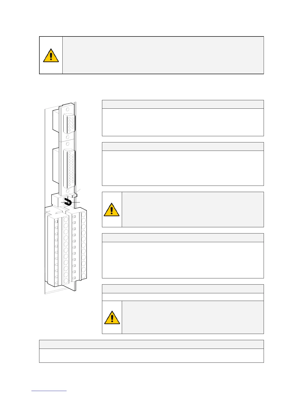
10.2.1 Customer Interface
Serial port J3 - RS232 (sub - D - female 9 pin)
Total remote management of the system using software GE
Power Diagnostics, GE Data Protection or GE Service
Software for system protection and management of the UPS
systems.
Pin 2: TX (out)
Pin 3: RX (in)
Pin 5: GND
J2 (sub – D female 25p) – Output signals on voltage-free contacts
J2 / 1, 2, 3
NO, C, NC Mains failure (def. Parameter RL=1)
J2 / 4, 5, 6
NO, C, NC Load on inverter (def. Parameter RL=3)
J2 / 7, 8, 9
NO, C, NC Stop operation (def. Parameter RL=5)
J2 / 14, 15, 16
NO, C, NC Load on mains (def. Parameter RL=2)
J2 / 17, 18, 19
NO, C, NC General alarm (NO) (def. Parameter RL=4)
J2 / 20, 21, 22
NO, C, NC Buzzer
(def. Parameter RL=6)
Signals on terminals X1 and on connector J2 are in parallel and
therefore not separated galvanically from each other.
The programmable signals on X1 and J2 will be disabled with Q1
open, with the exception of the signals for:
16 – Manual bypass ON
24 – Relay output ON
25 – Relay output OFF
26 – EPO
X1 – Output signals on voltage-free contacts
X1 / 1, 2, 3
NO, C, NC
Mains failure
(def. Parameter RL=1)
X1 / 4, 5, 6
NO, C, NC
Load on inverter
(def. Parameter RL=3)
X1 / 7, 8, 9
NO, C, NC
Stop operation
(def. Parameter RL=5)
X1 / 12, 13, 14
NO, C, NC
Load on mains
(def. Parameter RL=2)
X1 / 15, 16, 17
NO, C, NC
General alarm (NO)
(def. Parameter RL=4)
X1 / 18, 19, 20
NO, C, NC Buzzer
(def. Parameter RL=6)
X2 – Terminals EPO connection (Emergency Power Off)
X2 / 1, 2 (or J2 / 12, 25)
NC EPO (Emergency Power Off)
SGT4000_customer interface_01
1
2
3
4
567891011
1615
14
1312 222120191817
J3
J2
X1
21
JP3
X2
Fig. 10.2.1-1 Customer Interface
C = Common
NO
= Normally Open
NC
= Normally Closed
To enable this function, remove jumper JP3 on the Customer
Interface and the cable on the terminal X2 / 1, 2.
(See Fig. 10.2.1-1).
Verify if the cable on the terminal X7 / 1, 2 and jumper JP8 on the
control board P2 – Mainboard are OFF (see Fig. 10.2.1-3).
Programmable functions on input contacts
X1/10, 21 or J2/10, 23
Programmable
X1/11, 22 or J2/11, 24
Programmable / Generator ON (NO)

 Loading...


