Modifications reserved Page 76/103
OPM_LPS_33E_60K_M12_2GB_V010.doc Operating Manual LP 33 Series 60-80-100-120 kVA / S2
8.1.3 From Manual Bypass Q2 to normal function VFI
This procedure presupposes that the load is powered by the manual bypass switch, and:
• The inverter is switched OFF;
• The manual bypass switch Q2 is closed (Pos. I);
• The output switch Q1 is open (Pos. 0);
• The external battery fuses are removed;
• LED Alarm blinks.
NOTE !
This procedure must not be performed if the UPS is used as frequency converter.
1. Insert the external battery fuses.
In case of GE battery cabinet: insert the fuses in their place and close fully the cover of fuse-
holder by using correctly the handle.
2. Close the output switch Q1 (Pos. I).
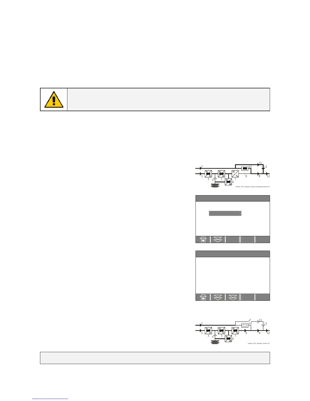
Load is now supplied parallel through automatic bypass and
manual bypass Q2.
The synoptic diagram must display the status “LOAD SUPPLIED BY
AUTOMATIC BYPASS AND MANUAL BYPASS Q2”.
REQUEST TOTAL OFF
3. Only in case it has been previously activated, restore the
command “Total Off” by entering the screen:
COMMANDS/RESET TOTAL OFF
V
`Home\Meter
BOOSTER
f : 50.0 Hz
L1 : 397 V
L2 : 395 V
L3 : 393 V
Vp : 400 V
Vn : 400 V
4. Open the manual bypass switch Q2 (Pos. 0).
The load is supplied by the mains through the automatic bypass.
Verify, selecting the screen METERING/BOOSTER/Vp and Vn, that the
booster voltage has reached about 400 Vdc.
5. Insert the inverter by pressing “Inverter ON” ( I ) key.
Some seconds later the load will be transferred on inverter.
LED Alarm turn Off and the LED Operation must be lit.
The synoptic diagram must display the status “LOAD SUPPLIED BY
INVERTER”.

 Loading...


