Modifications reserved Page 41/103
OPM_LPS_33E_60K_M12_2GB_V010.doc Operating Manual LP 33 Series 60-80-100-120 kVA / S2
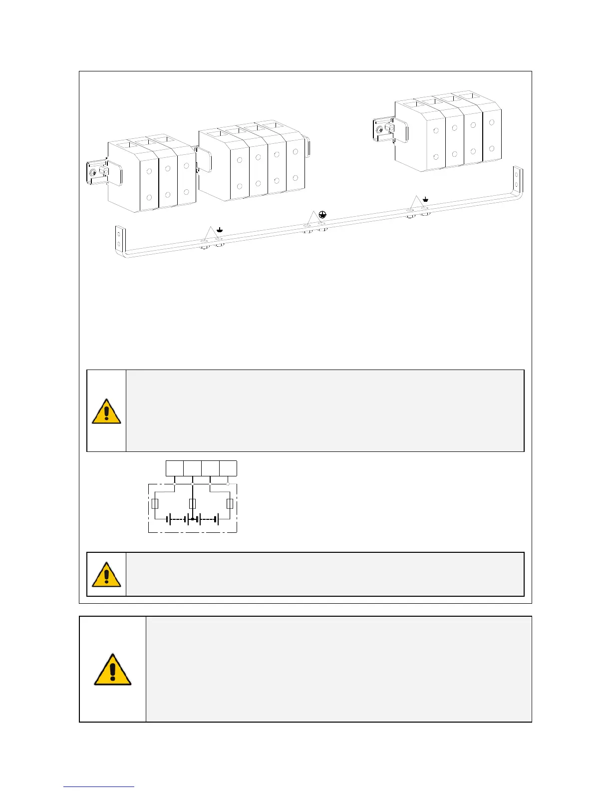
5.8.3 LP 33 Series 100 - 120 kVA - Power connection with common input mains
L
P
S
3
3
_
1
0
0
-
1
2
0
_
S
2
_
C
o
n
n
e
c
t
i
o
n
c
o
m
m
o
n
_
E
M
C
_
0
1
X4
Battery
L1-1
-
0
+
X1
Mains 1
X3
Load
L2-1
L3-1
N1
L1
L2
L3
N2
PE
PE
PE
Fig. 5.8.3-1 Terminals for common input mains
X1 Mains 1 - Mains input connection
L1-1 = Rectifier + Bypass Phase L1
L2-1 = Rectifier + Bypass Phase L2
L3-1 = Rectifier + Bypass Phase L3
N = Mains Neutral
PE = Main ground
X3 Load - Load output connection
L1 = Load Phase L1
L2 = Load Phase L2
L3 = Load Phase L3
N = Load Neutral
PE = Load Ground
NOTE !
Max. rating X1 – X3 - X4 terminals: 150mm
2
.
Input/output terminals must be tightened with a proper screwdriver applying
torsion force 10 Nm.
Main ground (PE) cables must be connected to bus bar with M8 bolts.
Torque wrench at 22Nm.
LPS33_040-120_Connection battery_01
+
0
-
+
0
-
X4
PE
Fig. 5.8.3-2 External battery connection
X4 Battery - External battery connection
- = Negative pole of the battery
0 = Central point of battery blocks
+ = Positive pole of the battery
PE = Battery cabinet ground
WARNING !
Before closing the “external battery fuses”, verify for correct polarity of the battery
connection.
NOTE !
To meet standards concerning electromagnetic compliance, the connection
between the UPS and external Battery must be done by using a shielded cable or
suitable shielded (metal) conduit!
This UPS is only designed to operate in a wye-configured electrical system with a
solidly grounded neutral.
If the UPS is equipped with an input transformer, the secondary of the
transformer must be wye-configured with neutral solidly grounded.

 Loading...


