Modifications reserved Page 100/103
OPM_LPS_33E_60K_M12_2GB_V010.doc Operating Manual LP 33 Series 60-80-100-120 kVA / S2
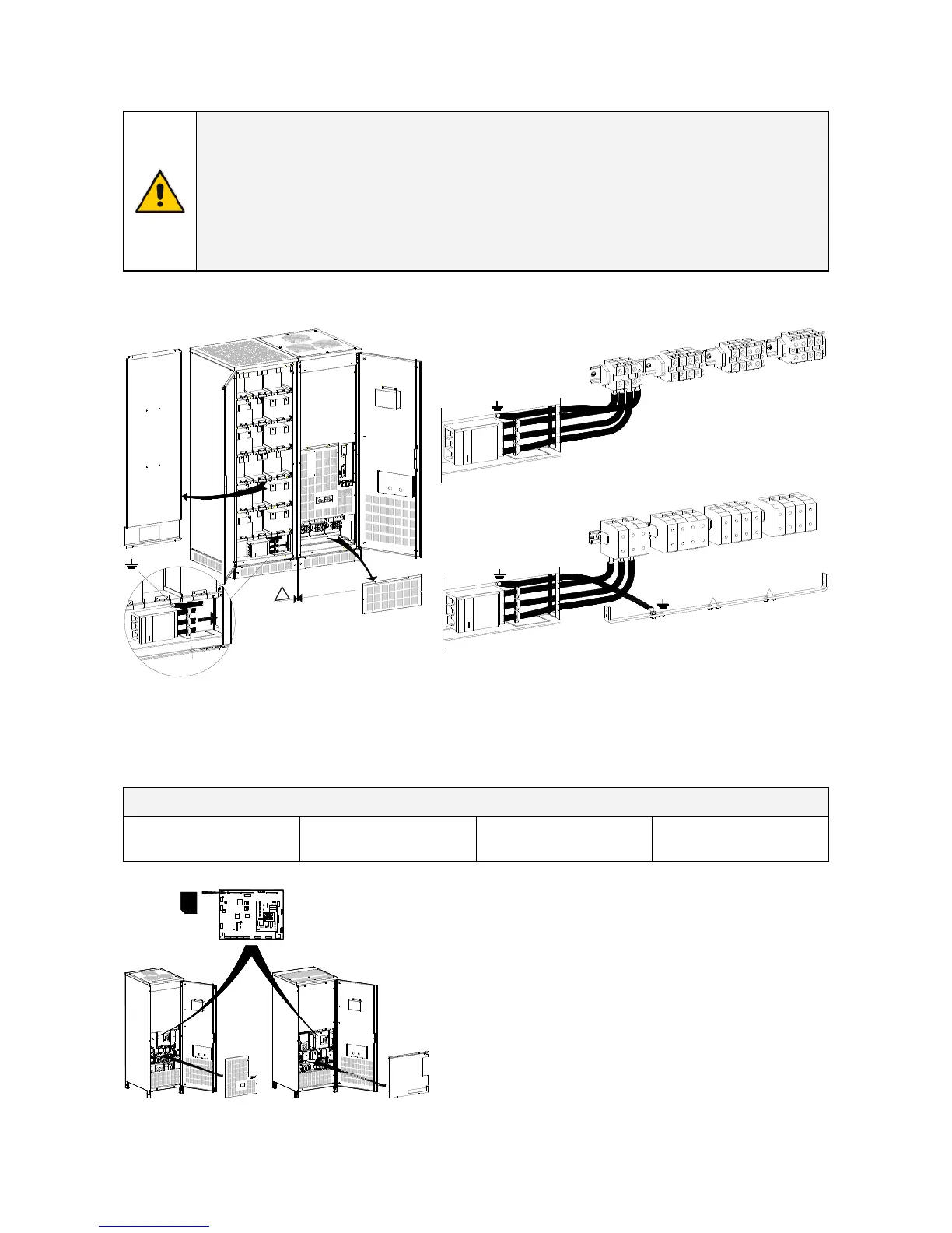
10.2.2 Optional battery cabinet connection
WARNING !
The installation and cabling of the options must be performed by
QUALIFIED SERVICE PERSON.
Make sure that the UPS installation is completely powered down and the cabinet
battery fuses must be open.
Check for sufficient floor loading capacity (see Technical Data Sheet).
Before closing the battery fuses verify for correct polarity of the battery connection.
The battery cabinet, with standard cables, must be located on the left side of the UPS (see Fig. 10.2.2-1).
L
P
S
3
3
_
0
6
0
-
0
8
0
_
S
2
_
C
o
n
n
e
c
t
i
o
n
b
a
t
t
e
r
y
c
a
b
i
n
e
t
_
0
1
Mains 1
X4
Battery
Load
X1
X3
L1-1
L2-1
L3-1
N1
PE
L1
L2
L3
N2
PE
-
0
+
PE
Mains 2
X2
L1-2
L2-2
L3-2
N
_
0
_
PE
LP 33 Series 60 - 80 kVA
Mains 1
X4
Battery
Load
X1
X3
Mains 2
X2
LP 33 Series 100 - 120 kVA
PE
L
P
S
3
3
_
1
0
0
-
1
2
0
_
S
2
_
C
o
n
n
e
c
t
i
o
n
b
a
t
t
e
r
y
c
a
b
i
n
e
t
_
0
1
_
0
_
L1-1
-
0
+
L2-1
L3-1
N1
L1-2
L2-2
L3-2
L1
L2
L3
N2
PE
PE
N
PE
M
a
x
.
5
m
m
/
2
"
OFF
ON
OFF
ON
!
_
0
_
_
0
_
A
PE
L
P
S
3
3
_
0
6
0
-
0
8
0
_
S
2
_
U
P
S
+
b
a
t
t
e
r
y
c
a
b
i
n
e
t
_
0
1
Main ground (PE) cables must be connected to bus-bar
with M8 bolts
Clamp the cables with the included cable-ties “A”.
X4 Battery - External battery connection
- = Negative pole of the battery
0 = Central point of battery blocks
+ = Positive pole of the battery
PE = Battery cabinet ground
Fig. 10.2.2-1 Optional battery cabinet assembly and connection
External battery fuses
LP 33 Series 60 kVA LP 33 Series 80 kVA LP 33 Series 100 kVA LP 33 Series 120 kVA
3x125Agl – 550Vdc – NH00 3x160Agl – 550Vdc - NH00
3x200Agl – 440Vdc – NH1 3x250Agl – 440Vdc – NH1
OFF
ON
OFF
ON
LPS33_060-120_S2_UPS+P1-J28_01
J28
P1 - Control board
Q2
ON
OFF
Q2
ON
OFF
LP 33 Series 60 - 80 kVA LP 33 Series 100 - 120 kVA
Fig. 10.2.2-2 PCB P1 – Control board
Connect the Battery temperature probe J28 to the P1
– Control board.
This probe compensates the battery charging current
in function of the ambient temperature of the
battery.
The cable with the connector J28 must be laid in a
separated conduit protected from the external
electromagnetic fields.

 Loading...


