Modifications reserved Page 99/103
OPM_LPS_33E_60K_M12_2GB_V010.doc Operating Manual LP 33 Series 60-80-100-120 kVA / S2
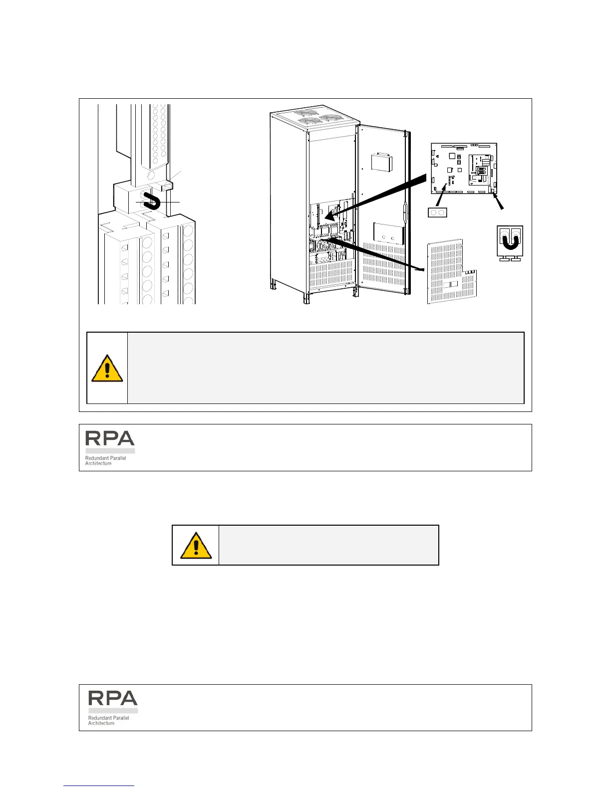
EPO (Emergency Power Off)
An external Emergency switch (NC - Normally Closed voltage-free contact) can be connected on
terminals X2 / 1, 2 or connector J2 / 12, 25 of the Customer Interface (see Fig. 10.2.1-1 / X2 & J2).
J2
X1
21
JP3
X2
Fig. 10.2.1-2 PCB Customer Interface
L
P
S
3
3
_
0
6
0
-
0
8
0
_
S
2
_
U
P
S
+
X
7
+
J
P
5
_
0
1
OFF
ON
OFF
ON
12
X7
P1 - Control board
JP5
Fig. 10.2.1-3 PCB P1 – Control board
NOTE !
To enable this function, remove jumper JP3 on the Customer Interface and the cable
on the terminal X2 / 1, 2 (see Fig. 10.2.1-2).
Verify if the cable on the terminal X7 / 1, 2 and jumper JP5 on the P1 – Control board
are OFF (see Fig. 10.2.1-3).
In a Parallel System a separate NC (Normally Closed) contact must be connected
individually to each unit.
When activated, this switch causes the immediate shutdown of booster, battery-charger, inverter; and
the contactors K4, K6 and K7.
NOTE !
This procedure could imply a load shutdown.
When the EPO has been activated, the system must be restored as follows:
• Press the push-button EPO (contact on X7 / 1, 2 is closed again).
• Press the key “O” (Inverter OFF – see Section 6.2) on the control panel.
• Press the key “I” (Inverter ON – see Section 6.2) on the control panel.
In case of a Parallel System press the key “O” (Inverter OFF) on the control panel of
each unit connected on the parallel bus and having its output switch Q1 closed.

 Loading...


