Modifications reserved Page 37/103
OPM_LPS_33E_60K_M12_2GB_V010.doc Operating Manual LP 33 Series 60-80-100-120 kVA / S2
5.8 ELECTRICAL CONNECTION
WARNING !
The connections to and from the UPS must be executed by QUALIFIED PERSONNEL
ONLY.
Refer to the “Safety prescriptions” described on Section 1.
Carefully read the following recommendations before proceeding:
• Ensure that the AC and DC external isolators are Off, and prevent their inadverted operation.
• Do not close any external isolators prior to the commissioning of the equipment.
• The input/output cables must be put in order and fixed, taking care to avoid risk of short-circuit
between different poles.
• The earthing and neutral connection of the electrical system must be in accordance with local
regulations.
• In case of additional cabinets containing batteries, filters, input/ output transformers, etc, the earth
must be connected to the UPS main earth.
• Once the power cables have been connected, re-install the internal safety shields and close the
cabinets by re-installing all external panels.
OFF
ON
B
A
C
D
OFF
ON
L
P
S
3
3
_
0
6
0
-
0
8
0
_
S
2
_
C
o
n
n
e
c
t
i
o
n
_
0
1
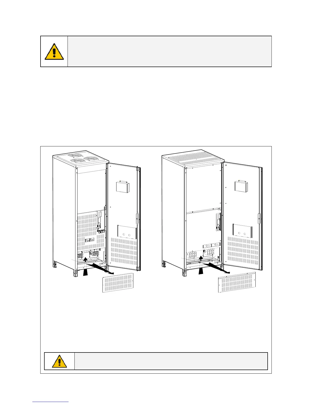
Fig. 5.8-1 LP 33 Series 60 - 80 kVA
Power IN / OUT connections
ON
OFF
Q1
ON
OFF
B
A
C
D
Q2
L
PS
3
3
_
1
0
0
-
1
2
0
_
S2
_
C
o
n
n
e
c
t
i
o
n
_
0
1
Fig. 5.8-2 LP 33 Series 100 - 120 kVA
Power IN / OUT connections
Access to the AC terminals
1 - Open the front door “A” of the UPS cabinet.
2 - Remove the front panel “B”.
3 - Cut an opening into rubber “C” to allow cable passage.
4 - Fix the cables on profile “D” with the enclosed cable ties.

 Loading...


