Modifications reserved Page 94/103
OPM_LPS_33E_60K_M12_2GB_V010.doc Operating Manual LP 33 Series 60-80-100-120 kVA / S2
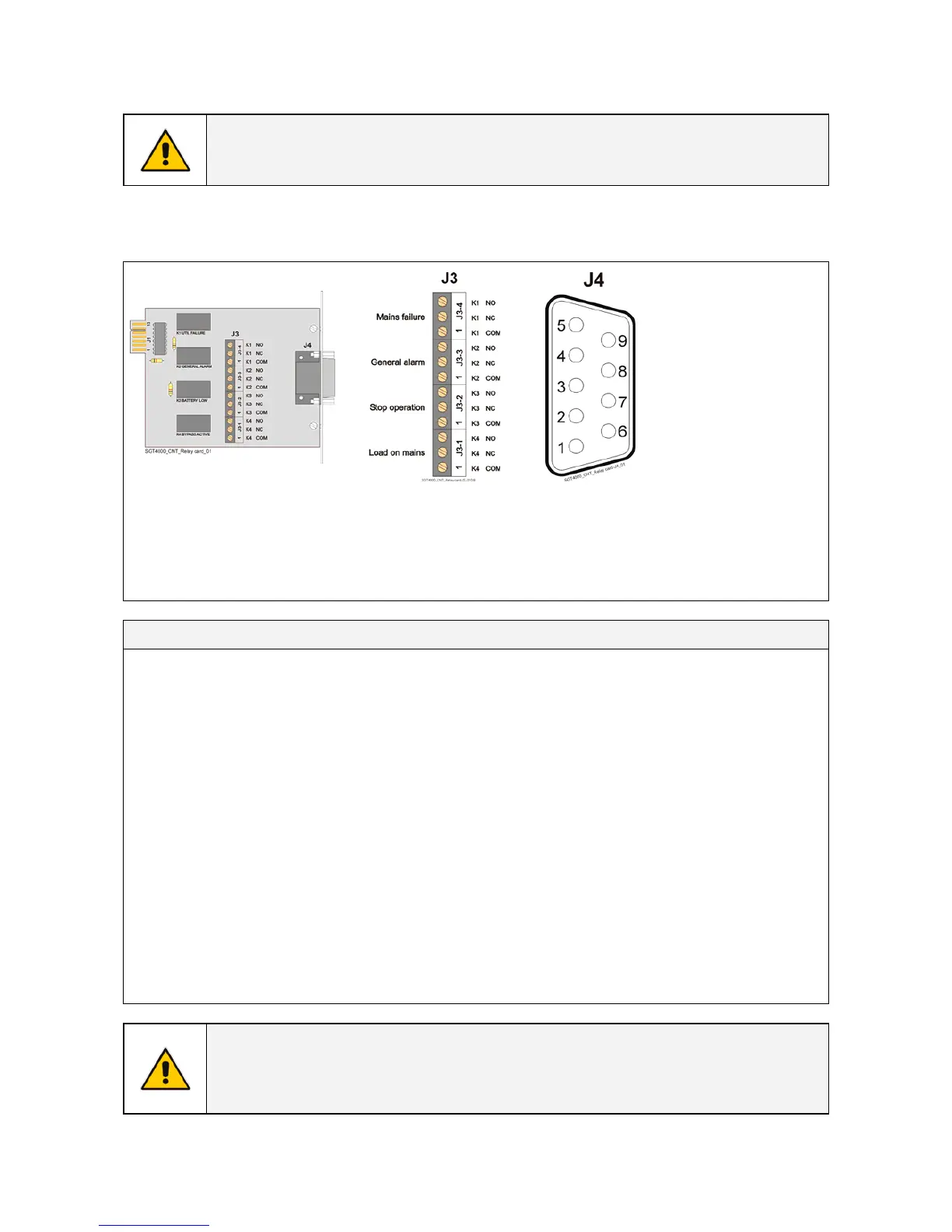
9.2 RELAY CARD
WARNING !
Connections described in this chapter shall be done only by a trained person or
SERVICE ENGINEERS.
The Relay Card, allows the programming of 4 output channels on dry contacts, which can be read on
either terminal J3 or plug J4 (sub - D - male 9 pin).
1
2
3
General alarm (NO)
4
Mains failure (NC)
5
C (common)
6
Load on mains (NO)
7
Stop operation
8
C (common)
9
Mains failure (NO)
NO = Normally Open C = Common NC = Normally Closed
Voltage free contacts: Max.: 60Vdc or 30Vac / 0.5A
Min. signal level: 5Vdc / 5mA
Fig. 9.2-1 Relay Card
Output signals on voltage-free contacts
On terminals J3 or J4 connector 4 of the following 28 signals can be selected from the display
(access only with password): SETUP / SETUP / LEVEL 2: SERVICE.
0 - No signal 15 -
Battery discharge
1 - Buzzer 16 -
Manual bypass ON
2 - General alarm (NO) 17 -
Rectifier ON
3 - Load on mains 18 -
Inverter ON
4 - Stop operation 19 -
Battery boostcharge
5 - Load on inverter 20 -
Battery earth fault
6 - Mains failure 21 -
Battery fault
7 - DC overvoltage 22 -
Relay input 1
8 - Low battery 23 -
Relay input 2
9 - Overload 24 -
Relay output ON
10 - Overtemperature 25 -
Relay output OFF
11 - Inverter-mains not syncrony 26 -
EPO (Emergency Power Off)
12 - Bypass locked 27 -
ECO Mode ON
13 - Bypass mains failure 28 -
General alarm (NC)
14 - Rectifier mains failure
NOTE !
The function GEN-ON is not available on the Relay Card.
In case this function is needed, the optional Customer Interface card must be
installed (see Section 10.2.1).

 Loading...


