Modifications reserved Page 45/103
OPM_LPS_33E_60K_M12_2GB_V010.doc Operating Manual LP 33 Series 60-80-100-120 kVA / S2
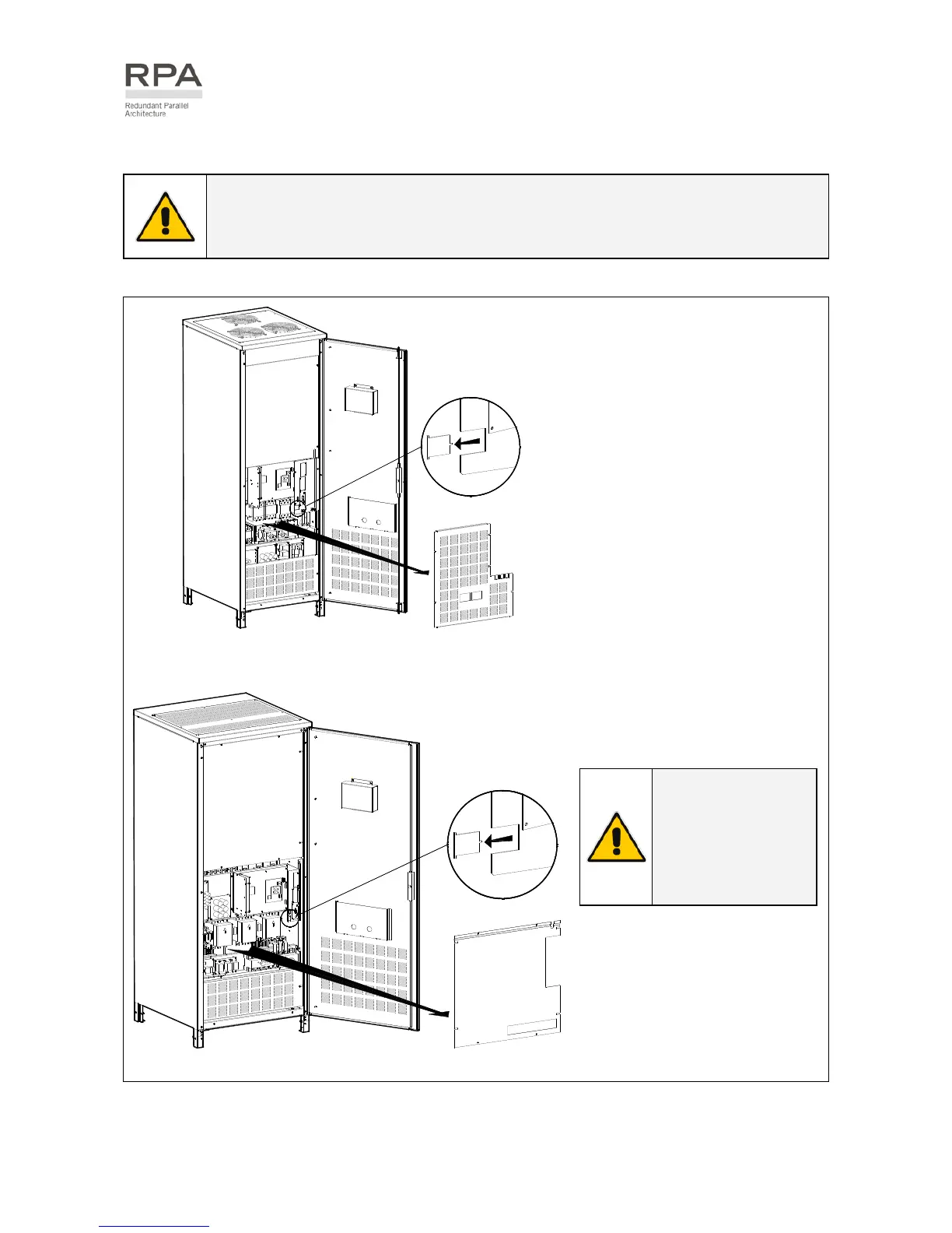
5.8.7 RPA Parallel System - Control bus connection
WARNING !
This operation must be performed by trained personnel before the initial start-up
(ensure that the UPS installation is completely powered down).
L
P
S
3
3
_
0
6
0
-
0
8
0
_
S
2
_
R
P
A
c
o
n
n
e
c
t
i
o
n
_
0
1
B
A
OFF
ON
OFF
ON
C
D
Fig. 5.8.7-1 LP 33 Series 60 - 80 kVA - Access to the RPA board
Access to the RPA board
1 - Open the front door “A” of the
UPS cabinet.
2 - Remove the front panel “B”.
3 - Remove with appropriate tool
the metallic window “C” from
the metal screen “D”.

 Loading...


