1-6 MM2 Motor Manager 2
GE Power Management
1.3 SPECIFICATIONS 1 INTRODUCTION
1
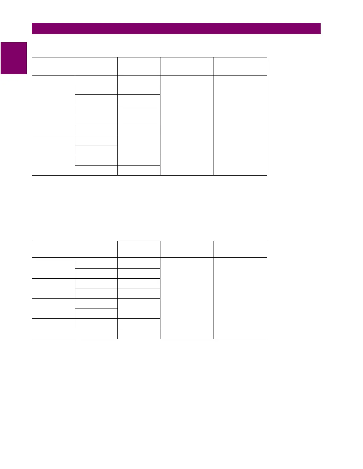
MM2 CONTACTOR A & B AND AUX 2 OUTPUT RELAY CONTACTS
CONFIGURATION: CONTACTOR A AND B: Form A
AUX RELAY 2: Form C
CONTACT MATERIAL: Silver Alloy (AgCdO)
MAX. OPERATING VOLTAGE: 280 V AC, 250 V DC
MAXIMUM PERMISSIBLE LOAD: 5 V DC, 100 mA
MM2 AUX 1 OUTPUT RELAY CONTACTS
CONFIGURATION: Dual Form C
CONTACT MATERIAL: Silver Alloy (AgCdO)
MAX. OPERATING VOLTAGE: 280 V AC, 125 V DC
UNDERVOLTAGE – SUPPLY VOLTAGE
UNDERVOLTAGE: 65% of nominal (120 V AC or 240 V AC);
Immediate restart for maximum dip time of 0.1 to 0.5 seconds or OFF;
Delayed restart for maximum dip time of 0.1 to 10.0 seconds or UNLIMITED time
DELAY RESTART RANGE: 0.2 to 300 seconds
DELAY RESTART ACCURACY: ±0.2 seconds
VOLTAGE BREAK MAKE/CARRY
CONTINUOUS
MAKE/CARRY
0.2 seconds
RESISTIVE
30 V DC 10 A
10 A 30 A
125 V DC 0.5 A
250 V DC 0.3 A
INDUCTIVE
(L/R = 7 ms)
30 V DC 5 A
125 V DC 0.25 A
250 V DC 0.15 A
RESISTIVE
120 V AC
10 A
240 V AC
INDUCTIVE
(PF = 0.4)
120 V AC 10 A
225 V AC 8 A
VOLTAGE BREAK MAKE/CARRY
CONTINUOUS
MAKE/CARRY
0.2 seconds
RESISTIVE
30 V DC 5 A
5 A 15 A
125 V DC 0.25 A
INDUCTIVE
(L/R = 7 ms)
30 V DC 2.5 A
125 V DC 0.1 A
RESISTIVE
120 V AC
5 A
240 V AC
INDUCTIVE
(PF = 0.4)
120 V AC 5 A
225 V AC 3 A

 Loading...


